
No products
Product successfully added to your shopping cart
There are 0 items in your cart. There is 1 item in your cart.
3ctest Lightning Test Systems
- EMC Test Equipment
- Transient Generators
- RF Power Amplifiers
- DC - 300 kHz RF Amplifiers
- 10 kHz - 250 MHz RF Amplifiers
- 10 kHz - 400 MHz RF Amplifiers
- 10 kHz - 1 GHz RF Amplifiers
- 80 MHz - 1 GHz RF Amplifiers
- 1 GHz - 2 GHz RF Amplifiers
- 700 MHz - 4.2 GHz RF Amplifiers
- 1 GHz - 6 GHz RF Amplifiers
- 2 GHz - 8 GHz RF Amplifiers
- 6 GHz - 18 GHz RF Amplifiers
- 18 GHz - 40 GHz RF Amplifiers
- Pulse Amplifiers
- RF Field Strength Probes & Meters
- RF Conducted Immunity
- EMC Receivers/EMI Analyzers
- EMC Antennas
- Coupling Decoupling Networks (CDN's)
- Line Impedance Stabilization Networks (LISN's)
- RF Test Equipment
- EMC Probes
- EMC Measurement & Equipment Software
- Power Supplies
- Electrical Safety Analyzers
- High Precision Laboratory Power Analyzers & Meters
- Anechoic Chambers
- Over-the-Air (OTA) Test Chambers
- EMI RF Shielded Tent Enclosures
- RF Shielded Rooms
- EMC Absorber
- Positioning Equipment
- EMC/EMI Test Setup
- GTEM Cells / TEM Cells
- Reverberation Chambers
- Used RF Anechoic Chambers
- EMC Chamber Filters
- EMC Chamber Shielding Gaskets
- RF Shielded Doors
- Anechoic Chamber Accessories
- Fully Anechoic (FAR) Test Chambers
- Manufacturers
- 3ctest
- AE Techron
- AH Systems
- Amplifier Research
- Boonton
- Com-Power
- Diamond Engineering
- EM Test (Ametek CTS)
- EMC Partner
- EMC Test Design
- Empower High Power RF Amplifiers
- ETS-lindgren
- Log Periodic Dipole Array Antenna
- Near Field Probe Sets
- Double Ridge Horn Antennas
- Biconical Antennas
- Quad Ridge Horn Antennas
- Electric Field Probes
- GTEM's
- Positioners & Tripods
- Loop Antennas
- Biconilog Antennas
- LISN's (Line Impedance Stabilization Network)
- Shielded Enclosures/Rooms
- Monopole Antennas
- Field Generating Antennas
- Fischer Custom Communications
- Haefely Hipotronics
- Haefely EFT/Burst Immunity Test Systems
- Haefely Surge Combination Wave Test Systems
- Haefely Surge Damped Oscillating Wave Test Systems
- Haefely Electrostatic Discharge Test Systems (ESD)
- Haefely Surge Ring Wave Test Systems
- Haefely Surge Telecom Wave Test Systems
- Haefely Magnetic Field Test Systems
- Haefely CDN's (Coupling/Decoupling Networks)
- IFI Amplifiers
- Keysight (Agilent)
- MVG - Microwave Vision Group
- PMM / Narda
- Rohde & Schwarz RF Test Equipment
- Rohde & Schwarz Broadband RF Amplifiers
- Rohde & Schwarz Spectrum Analyzers
- Rohde & Schwarz Compliant EMI Test Receivers
- Rohde & Schwarz Isotropic RF Probes
- Rohde & Schwarz RF Signal Generators
- Rohde & Schwarz RF Switches
- Rohde & Schwarz Oscilloscopes
- Rohde & Schwarz RF Power Meters
- Rohde & Schwarz RF Power Sensors
- Schloder
- Schwarzbeck Mess-Elektronik
- Schwarzbeck Antennas
- Schwarzbeck Automotive Antennas
- Schwarzbeck Broadband Horn Antennas
- Schwarzbeck Biconical Antennas
- Schwarzbeck Logarithmic Periodic Broadband Antennas
- Schwarzbeck Stacked Log-Periodic Broadband Antennas
- Schwarzbeck Biconic Log-Periodic Antennas
- Schwarzbeck Dipole Antennas
- Schwarzbeck Rod Antennas
- Schwarbeck Antenna Baluns / Holders
- Schwarzbeck LISN Line Impedance Stabilisation Networks
- Schwarbeck Decoupling & Absorbing Clamps
- Schwarzbeck Field Probes
- Schwarzbeck Helmholtz Coils
- Schwarzbeck Antenna Masts
- Schwarzbeck Coupling/Decoupling Networks
- Schwarzbeck Antennas
- Solar Electronics
- Teseq (Schaffner)
- Teseq Automotive Transient Generators
- Teseq RF Test Equipment
- Teseq EFT/Burst Generators
- Teseq RF Immunity Generators
- Teseq ESD Guns
- Teseq Surge Generators
- Teseq Harmonics & Flicker Solutions
- Teseq Dips, Interrupts & Variations Equipment
- Teseq Ring Wave Generators
- Teseq Oscillatory Waves Generators
- Teseq Absorbing Clamps / Ferrite Tube
- Teseq EMC Antennas
- Teseq Current Probes
- Teseq Coupling Networks
- Thermo Keytek
- Vicreate
- Compliance Standards
- International (IEC/EN)
- EN/IEC 61000-3-2
- EN/IEC 61000-3-3
- IEC 61000-3-11
- IEC / EN 610000-3-12
- EN/IEC 61000-4-2
- EN/IEC 61000-4-3
- EN/IEC 61000-4-4
- EN/IEC 61000-4-5
- EN/IEC 61000-4-6
- EN/IEC 61000-4-7
- EN/IEC 61000-4-8
- EN/IEC 61000-4-9
- EN/IEC 61000-4-10
- EN/IEC 61000-4-11
- EN/IEC 61000-4-12
- EN/IEC 61000-4-16
- EN/IEC 61000-4-18
- EN/IEC 61000-4-19
- EN/IEC 61000-4-20
- EN/IEC 61000-4-21
- EN/IEC 61000-4-29
- EN/IEC 61000-4-31
- IEC 61000-4-39
- EN/IEC 62132
- SEMI F47 Voltage Sag Immunity
- Product Standards
- Military & Aerospace Standards
- Automotive EMC Standards
- CISPR Standards
- Telecom Testing
- ANSI/IEEE Standards
- FCC Part 15
- FCC Part 30
- International (IEC/EN)
- Application/Test Type
- Radiated Immunity
- Bulk Current Injection Testing
- RF Emissions Testing
- Conducted Immunity
- Conducted Emissions
- Antenna Pattern Measurement
- CE Mark Testing
- Intentional Radiator Testing
- Pulsed HIRF Radar
- Over-the-Air (OTA) Testing
- 5G Test Solutions
- Automotive EMC
- SAR Measurement Equipment
- Radiated Emissions
- Battery Simulator Test Equipment
- Services
- Clearance
Viewed products
-

3ctest LCG 464C...
Lightning Test Flow Chart High...
 View larger
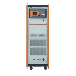
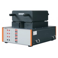
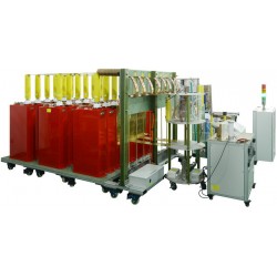
3ctest LCG 464C Lightening Direct Effect Test System
New
- Lightning Test Flow Chart
- High voltage attachment points partition test system
- Produce over temperature
- High voltage and strong electromagnetic force to cause the aircraft to be on fire
Standard:
- MIL-STD-464C
- HB6129-1987
- GJB 3567-1999
- SAE ARP5412
- RTCA/DO-160section23
PDF Downloads
Test Equipment Description
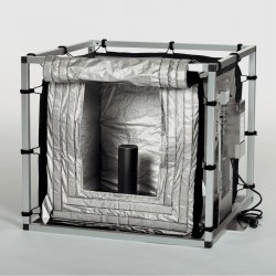
Aircraft is vulnerable to lightening direct adhesion in severe convection weather, which will produce over temperature, high voltage and strong electromagnetic force to cause the aircraft to be on fire, corrosion, explosion, structure distortion and strength reduction, etc. The lightening direct effect test system our company independent research and develop is a very complicated pulse current test system, mainly used in lightening direct effect tests for system, components and materials as per national military standards like GJB1389A,GJB3567, also American military standards MIL-STD-464C, ARP5412 and DO160 section23, etc. This system can be used for aircraft, aerospace materials, naval ships, missile, military vehicles and radar.
This lightening direct effect test system includes high voltage attachment points partition test system and high current physical damage test system. High voltage attachment points partition test system can simulate the possibility that equipments like aircraft are lightening attacked in different areas on the surface of aircraft and find the attachment points which are vulnerable to lightening attack. High current physical damage test system can be used to simulate the damage effect of aircraft structure caused by the over temperature and strong electromagnetic force which are produced when the attachment points are suffered to high current.
Lightning Test Flow Chart
This system can be configured according to customers test requirements and provide full test solutions.

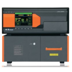
High Voltage Attachment Ppoints Partition Test System
This system is composed of three parts including high voltage generator, waveform regulation unit and control measurement system, four kinds of waveforms A, B, C, D are output by regulating different waveform regulation units, meet MIL-STD-464C , DO160 S23 and other standards about direct lightning high voltage test, also used for other similar lightning and withstand voltage tests and research.
Waveform Parameter Definition
According to MIL-STD-464C and SAE ARP5412, etc, four voltage waveforms shown as below:

Requirements:
A component rising slope: 1000(-0+50%)kV/μs, rising stop when test device breakdown or flashover and turn to zero. If no flashover for test device, there is no regulation for the waveform drop.
B component open circuit voltage waveform with rising slope: 1.2μs (±20%) and duration: 50μs(±20%)
C component the voltage waveform cut off at 1.2μs, no requirements for rise time and peak value.
D component open circuit voltage waveform with rising slope: 50-250μs and duration: >2000μs. The waveform is used for testing the time characteristic, when the waveform is used for the analysis of lightning attachment area probability, the conclusion is higher than the actual value.
| SPECIFICATIONS | ||||
| Technical Parameters of LVG3000 | ||||
| Output waveform | A waveform | B waveform | C waveform | D waveform |
| Front time | 1000(+500)kV/μs | 1.2μs±20% | 2μs±20% | 50-250μs |
| Decay time | -- | 50±20% | -- | 大于2000 |
| peak efficiency | >90% | >90% | >80% | >60% |
| Charging voltage | 200kV (two-side charging) | |||
| Levels | 15 | |||
| Discharging switch | copper ball , three-gap ignition | |||
| Switch type | linear driving 0~100mm adjustable, accuracy 0.1mm | |||
| Waveform shaping | Form a long wave tail by Crowbar feedback circuit | |||
| General Data | ||||
| Power supply | AC220V 100A | |||
| Charging voltage | 20~200kV | |||
| Polarity | +/- | |||
| Voltage measurement | Damped voltage divider | |||
| Features: | ||||
| • LVG 3000 with open style main circuit design and H shaped tower structure to achieve a compact size | ||||
| • Artistic and simple appearance | ||||
| • Parallel charging and series discharging by Max generator | ||||
| • Automatically adjust ball gap distance within the charging voltage, 0.1mm resolution adjustable | ||||
| • Automatic safety protection procedure, audible and visual alarm | ||||
High voltage attachment points partition test diagram:

(1)Max voltage generator
(2)Regulation waveform unit
(3)Measurement voltage divider
(4)Regulation waveform unit includes steep slope, chopped wave or operation wave
(5)Grounding plane
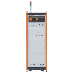
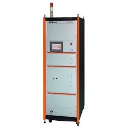
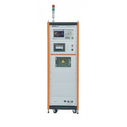
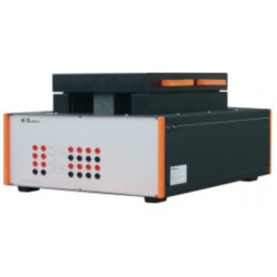
High current injection system
Aircraft is vulnerable to lightening direct adhesion in severe convection weather, which will produce over temperature, high voltage and strong electromagnetic force to cause the aircraft to be on fire, corrosion, explosion, structure distortion and strength reduction, etc. The aircraft lightning protection test system researched and developed independently by 3ctest is a very complicated pulse current test system, fully meets American military MIL-STD-464C, SAE ARP5412 and DO160 section23, the direct adhesion lightening area of the aircraft should bear the continuous waveforms composed of A, B, C and D, this system includes four pulse current generators.
- Six waveforms generated by four generators
- Charging polarity automatic switching by using rotating mechanism
- Electrical safety interlock, automatic short circuit capacitor and protect personal safety
- Non-gap Crowbar feedback circuit, waveform without oscillation
- Optical isolation of control signal between control and itself
- Every generator used independently with independent control system
- Many test modes can be programmed freely, meet kinds of test waveform requirements within test range
- Centralized control system can operate four generators and complete the test with one key
- High voltage switching by using multi-way air-operated units, waveforms switching over automatically
About Waveforms
Test waveforms include 6 waveforms: A, AH, B, C, C* and D, shown as below:

Component A: peak current 200kA±10%, action integral 2×10⁶A2·s±20% (within 500μs), rise time (10%-90% before peak)≤50μs, decay to 1% of peak wave≤500μs. Current could be one-way or oscillatory.
Component AH: peak current 150kA±10%, action integral 0.8×10⁶A2·s±20% (within 500μs), rise time (10%-90% before peak)≤37.5μs, decay to 1% of peak wave≤500μs. Current could be one-way or oscillatory.
Component B: current amplitude average 2kA±10%, max. electric charge<10C ± 10%, duration ≤5ms. Current could be one-way square wave or replaced by exponential current or linear decay current.
Component C: current amplitude 200-800A, electric charge 200C ± 20%, duration 0.25-1s. Current could be one-way square wave or replaced by exponential current or linear decay current.
Component C*: current amplitude average≥400A, duration = dwell time of combination wave -5ms. Duration of combination wave: 1-50ms. Current could be one-way square wave or replaced by exponential current or linear decay current.
Component D, peak current 100kA±10%, unidirectional current or oscillatory current, rise time (10%-90% before peak)≤25μs, decay to 1% of peak ≤500μs, action integral 0.25×10⁶A2·s±20% (within 500μs).
MIL-464C/DO-160G Section 23 Aircraft lightning protection system configuration:
This lightning system includes 5 set control system, 1 set measurement analysis system, 4 generators used to produce four components A, B, C, D, communication among generators by industry field bus to achieve independent experiments for 4 generators and centralized total control function.
Generator A and D use non-gap self-adaption Crowbar units, for non-gap Crowbar switch, there is no need to trigger by impulse voltage generator, no need to ignite by secondary delay control, it is a real self-adaption trigger. For non-gap switch, the noise is reduced greatly and the output reliability of equipments is improved.
Associated EMC Test Equipment

18 other products in the same category:
-
3ctest LSS 160SS Single Stroke Test System for DO-160 Section 22 Pulses 1, 4, 5A, 5B
-
3ctest LSS 160MS Multiple Stroke Lightning Transient Generator for DO-160 & MIL-STD-461G CS 117
-
3ctest SG3483 Multiple Waveform Lightening Surge Simulator for IEC 61000-4-5
-
3ctest CWS 600G & SPN 15100T High Voltage Lighting Surge Test System for EN/IEC 61000-4-5
-
3ctest ETS 160MB Multiple Burst Test System Waveform W2, W3, W6 for DO-160 Section 22
-

3ctest ETS 160MB Waveform Module for DO-160 Section 22 Testing
-

3ctest LSU-1 Low Level Waveform Attenuation Module for LSS160SS Lightning Generator
-
3ctest MD-W5B Module for LSS160 Series Lightning Test System
-
3ctest LCT-1 Current Coupling Transformer for LSS Series Lightning Testers, W1, W5A, W5B Current Wave Coupling up to 10 kA
-
3ctest LVT-1 Voltage Coupling Transformer for LSS Series Lightning Testers, W4, W5A, W5B Voltage Wave Coupling up to 1.6 kV
-
3ctest LVT-2 High Frequency Voltage Coupling Transformer for ETS160MB up to 4 kV
-
3ctest LVT-3 High Frequency Current Coupling Transformer for ETS160MB up to 160 Amps
-
3ctest CN-1 Mains Supply Coupling Unit for W4, W5A, W5B Surge Wave Coupling up to 420 Volts
-

3ctest DN 416T Mains Supply Decoupling Unit for Pin Injection W4, W5A, W5B Waveforms
-
3ctest LISN 3830 Linear Impedance Stability Network for RTCA/DO-160G up to 400V, 30A
-
3ctest LISN 45200 Linear Impedance Stability Network for RTCA DO-160 Section 22 up to 450V, 200A
-
3ctest C28000 Capacitor for LISN Cable Bundle DO-160 Section 22 Testing up to 400V, 28000 uF
-
3ctest LCG 5M Automatic Square Wave Impulse Current Test System