
No products
Product successfully added to your shopping cart
There are 0 items in your cart. There is 1 item in your cart.
CISPR 25 / ISO 7637 Automotive LISN's
- EMC Test Equipment
- Transient Generators
- RF Power Amplifiers
- DC - 300 kHz RF Amplifiers
- 10 kHz - 250 MHz RF Amplifiers
- 10 kHz - 400 MHz RF Amplifiers
- 10 kHz - 1 GHz RF Amplifiers
- 80 MHz - 1 GHz RF Amplifiers
- 1 GHz - 2 GHz RF Amplifiers
- 700 MHz - 4.2 GHz RF Amplifiers
- 1 GHz - 6 GHz RF Amplifiers
- 2 GHz - 8 GHz RF Amplifiers
- 6 GHz - 18 GHz RF Amplifiers
- 18 GHz - 40 GHz RF Amplifiers
- Pulse Amplifiers
- RF Field Strength Probes & Meters
- RF Conducted Immunity
- EMC Receivers/EMI Analyzers
- EMC Antennas
- Coupling Decoupling Networks (CDN's)
- Line Impedance Stabilization Networks (LISN's)
- RF Test Equipment
- EMC Probes
- EMC Measurement & Equipment Software
- Power Supplies
- Electrical Safety Analyzers
- High Precision Laboratory Power Analyzers & Meters
- Anechoic Chambers
- Over-the-Air (OTA) Test Chambers
- EMI RF Shielded Tent Enclosures
- RF Shielded Rooms
- EMC Absorber
- Positioning Equipment
- EMC/EMI Test Setup
- GTEM Cells / TEM Cells
- Reverberation Chambers
- Used RF Anechoic Chambers
- EMC Chamber Filters
- EMC Chamber Shielding Gaskets
- RF Shielded Doors
- Anechoic Chamber Accessories
- Fully Anechoic (FAR) Test Chambers
- Manufacturers
- 3ctest
- AE Techron
- AH Systems
- Amplifier Research
- Boonton
- Com-Power
- Diamond Engineering
- EM Test (Ametek CTS)
- EMC Partner
- EMC Test Design
- Empower High Power RF Amplifiers
- ETS-lindgren
- Log Periodic Dipole Array Antenna
- Near Field Probe Sets
- Double Ridge Horn Antennas
- Biconical Antennas
- Quad Ridge Horn Antennas
- Electric Field Probes
- GTEM's
- Positioners & Tripods
- Loop Antennas
- Biconilog Antennas
- LISN's (Line Impedance Stabilization Network)
- Shielded Enclosures/Rooms
- Monopole Antennas
- Field Generating Antennas
- Fischer Custom Communications
- Haefely Hipotronics
- Haefely EFT/Burst Immunity Test Systems
- Haefely Surge Combination Wave Test Systems
- Haefely Surge Damped Oscillating Wave Test Systems
- Haefely Electrostatic Discharge Test Systems (ESD)
- Haefely Surge Ring Wave Test Systems
- Haefely Surge Telecom Wave Test Systems
- Haefely Magnetic Field Test Systems
- Haefely CDN's (Coupling/Decoupling Networks)
- IFI Amplifiers
- Keysight (Agilent)
- MVG - Microwave Vision Group
- PMM / Narda
- Rohde & Schwarz RF Test Equipment
- Rohde & Schwarz Broadband RF Amplifiers
- Rohde & Schwarz Spectrum Analyzers
- Rohde & Schwarz Compliant EMI Test Receivers
- Rohde & Schwarz Isotropic RF Probes
- Rohde & Schwarz RF Signal Generators
- Rohde & Schwarz RF Switches
- Rohde & Schwarz Oscilloscopes
- Rohde & Schwarz RF Power Meters
- Rohde & Schwarz RF Power Sensors
- Schloder
- Schwarzbeck Mess-Elektronik
- Schwarzbeck Antennas
- Schwarzbeck Automotive Antennas
- Schwarzbeck Broadband Horn Antennas
- Schwarzbeck Biconical Antennas
- Schwarzbeck Logarithmic Periodic Broadband Antennas
- Schwarzbeck Stacked Log-Periodic Broadband Antennas
- Schwarzbeck Biconic Log-Periodic Antennas
- Schwarzbeck Dipole Antennas
- Schwarzbeck Rod Antennas
- Schwarbeck Antenna Baluns / Holders
- Schwarzbeck LISN Line Impedance Stabilisation Networks
- Schwarbeck Decoupling & Absorbing Clamps
- Schwarzbeck Field Probes
- Schwarzbeck Helmholtz Coils
- Schwarzbeck Antenna Masts
- Schwarzbeck Coupling/Decoupling Networks
- Schwarzbeck Antennas
- Solar Electronics
- Teseq (Schaffner)
- Teseq Automotive Transient Generators
- Teseq RF Test Equipment
- Teseq EFT/Burst Generators
- Teseq RF Immunity Generators
- Teseq ESD Guns
- Teseq Surge Generators
- Teseq Harmonics & Flicker Solutions
- Teseq Dips, Interrupts & Variations Equipment
- Teseq Ring Wave Generators
- Teseq Oscillatory Waves Generators
- Teseq Absorbing Clamps / Ferrite Tube
- Teseq EMC Antennas
- Teseq Current Probes
- Teseq Coupling Networks
- Thermo Keytek
- Vicreate
- Compliance Standards
- International (IEC/EN)
- EN/IEC 61000-3-2
- EN/IEC 61000-3-3
- IEC 61000-3-11
- IEC / EN 610000-3-12
- EN/IEC 61000-4-2
- EN/IEC 61000-4-3
- EN/IEC 61000-4-4
- EN/IEC 61000-4-5
- EN/IEC 61000-4-6
- EN/IEC 61000-4-7
- EN/IEC 61000-4-8
- EN/IEC 61000-4-9
- EN/IEC 61000-4-10
- EN/IEC 61000-4-11
- EN/IEC 61000-4-12
- EN/IEC 61000-4-16
- EN/IEC 61000-4-18
- EN/IEC 61000-4-19
- EN/IEC 61000-4-20
- EN/IEC 61000-4-21
- EN/IEC 61000-4-29
- EN/IEC 61000-4-31
- IEC 61000-4-39
- EN/IEC 62132
- SEMI F47 Voltage Sag Immunity
- Product Standards
- Military & Aerospace Standards
- Automotive EMC Standards
- CISPR Standards
- Telecom Testing
- ANSI/IEEE Standards
- FCC Part 15
- FCC Part 30
- International (IEC/EN)
- Application/Test Type
- Radiated Immunity
- Bulk Current Injection Testing
- RF Emissions Testing
- Conducted Immunity
- Conducted Emissions
- Antenna Pattern Measurement
- CE Mark Testing
- Intentional Radiator Testing
- Pulsed HIRF Radar
- Over-the-Air (OTA) Testing
- 5G Test Solutions
- Automotive EMC
- SAR Measurement Equipment
- Radiated Emissions
- Battery Simulator Test Equipment
- Services
- Clearance
Viewed products
-

Schwarzbeck NNHV...
High Voltage LISN according to to...
") View larger
View larger ")
")
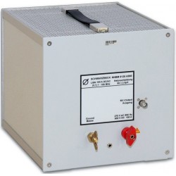
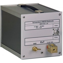
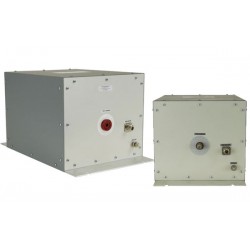
Schwarzbeck NNHV 8123-400 Single Path High Voltage AMN (LISN)
New
- High Voltage LISN according to to CISPR 25 Ed. 4 or BMW GS 95025-1
- To measure the conducted disturbance voltage on shielded lines for (hybrid) electric vehicles (HEV, EV), can be used for BCI with an external dummy load.
- Impedance (5µH) || 50 Ohm
- 400 A
- 1000 V (DC)
- Backside with built in 0.1 microfarad capacitor to ground
- N-jack
- Normally used in pairs inside the enclosure HVSE 8600!
PDF Downloads
Test Equipment Description
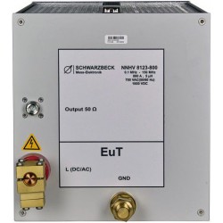
The main application of the unsymmetrical single path AMN (artificial mains network) NNHV 8123-400 is the measurement of interference voltage for electromobility purposes according to CISPR 25 edition 4 or BMW GS 95025-1 in the HF-VHF range 0.1 MHz – 150 MHz utilizing shielded cables. It can also be used for BCI tests using an external 50 Ω termination.
The impedance characteristics are basically realized by connecting an inductor in parallel with the input impedance of the measurement receiver: 5 µH || 50 Ω.
The LISN has been designed to be installed into a shielded housing HVSE 8600 in pairs. Each NNHV 8123-400 can be used to measure one single path. To be able to measure HV+ and HV- 2 units are required. The device under test has to be connected to the terminal at the front panel. The supply voltage has to be connected at the back panel. The shield is connected to the HVSE 8600 feedthrough.
The device under test may drain a continuous current of 250 A and for a short period of time it may even drain more than 500 A.

Principle circuit diagram of the NNHV 8123-400
Interference voltage measurements acc. to CISPR 25
Mains is connected at the back side. The 0.1 µF capacitor located at the backside is connected to ground. The device under test has to be connected to the front panel. The RFinterference voltage emitted by the equipment under test can be measured at the N-connector using an EMI receiver.
One LISN (that fits into a shielding enclosure HVSE 8600) has to be used for each path. The supply line has to be connected to the red terminal of one LISN and the return line has to be connected to the red terminal of the other LISN. The measurement port that is not being used at the moment has to be terminated with 50 Ω.
The RF-ground of both LISNs has to be connected to the GND-terminals. The GND connection with the massive brass wing terminals provides the mechanical and electrical connection to the housing HVSE 8600. To connect the inner conductor of the shielded cables with the red terminal of NNHV 8123-400 it is required to duct it through the outer housing at first. When the cable end is inside the housing the screw terminals are attached and the cables can be connected to NNHV 8123-400. Two pieces of screw terminals are within the scope of delivery of the NNBM 8123-400 series. The short RF-cables to connect the measurement outputs with the housing are within the scope of delivery of the shielded enclosure HVSE 8600.
Immunity tests with bulk current injection (BCI-tests):
The NNHV 8123-400 can be used for bulk current injection tests using suitable current injection clamps.
A sufficient air-circulation must be provided to avoid overheating of the LISN. Do not cover the LISN! The top and bottom hole-plates must not be covered to provide good air circulation. The external 50 Ω dummy load must be placed outside of the HVSE 8600 allowing good air circulation.
A light smell of coating and insulating material may appear in the first hours of operation, take care for not inhaling the emitted gas. The smell will disappear after some hours of operation at high temperature.
During bulk current injection tests danger may arise by high field strengths and temperatures (fire hazard!), therefore these tests must be performed by qualified personnel only! The relevant safety precautions must be considered!
The power injected at the EuT-terminals is being converted to heat inside the external 50 Ω terminating resistor. Please choose the power rating of the resistor according to the expected maximum of the RF-power!
Please note: The injected RF-power passes from the EuT-terminals directly to the Nconnector without any attenuation. Eventually connected RF-measuring equipment may be damaged!
Notice: As the circuitry is according to CISPR 16 there are high ground currents. It is normally not possible to use a LISN on power lines with ground current safety switches (They disconnect power due to excessive ground current). Either a special power line outlet without ground current safety switch must be installed (warning label required!), or an isolating power line transformer 1:1 must be used. In any case, ground-connect LISN before connecting to power line. Precise safety instructions must be provided to any user of the LISN.
Differences to the NNBM 8124 series:
The NNHV 8123 is used for measurements on shielded DuTs in the automotive industry. Low voltage DuTs which are connected with unshielded cables are measured with the NNBM 8124 series. Both types use a 5 µH inductor and the same diameter and distance of the terminals and the same housings. Existing calibration adapters can be used for both types of AMN - LV and HV. The circuitry is different at the input where the NNHV 8123 uses only 0.1 µF whilst the NNBM 8124 series uses 1 µF capacitors. Thus leaking currents to ground are lower in case of the NNHV 8123.
The NNHV 8123 series has no built in switchable termination as the NNBM 8124 series does. The immense heat dissipation caused by BCI testing can be kept outside the shielded housing in that way. The terminals of NNHV 8123 have no threads. They consist of multiple parts to provide a possibility to duct the cables through the housing. The NNBM 8124 uses wing terminals.
NNBM 8124 is usually not put into a shielded housing whilst the NNHV 8123 must be installed in pairs in the shielded housing NNHV 8600 to simulate the properties of shielded HV-networks in EV or HEV.
| Schwarzbeck NNHV 8123-400 Specifications | ||
| Frequency Range | 0.1 – 150 MHz | |
| Max. cont. current | 250 A | |
| Max. current (limited time) | 500 A | |
| Max voltage (DC) | 1000 V | |
| Max. voltage (AC 50/60 Hz) | 700 Vrms | |
| Max. voltage (AC 400 Hz) | 300 Vrms | |
| Impedance | 5 µH || 50 Ω (+/- 10%) | |
| DC-Resistance mains-EuT | < 1.3 mΩ | |
| Impedance (50 Hz) | 2 mΩ | |
| Impedance (400 Hz) | 12.6 mΩ | |
| EuT connectors | Screw terminal | |
| Clamping range HV-cable | 4 - 15 mm | |
| Measuring port | N-connector | |
| Dimensions (W x H x D) | 220 x 225 x 260 mm | |
| Weight | 6 kg | |
16 other products in the same category:
-
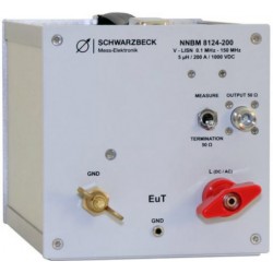
Schwarzbeck NNBM 8124-200 Single Path Vehicle AMN (LISN)
-
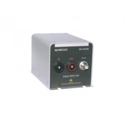
EM Test AN 200N100 Single line Artificial Network as per ISO 7637-2, CISPR25, ISO 11452 and CISPR16, switchable, 100A
-
Schwarzbeck NNBM 8126-A 890 Single Path Airborne Equipment LISN
-
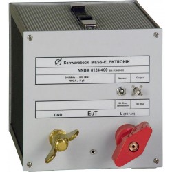
Schwarzbeck NNBM 8124-400 Single Path Vehicle AMN (LISN)
-
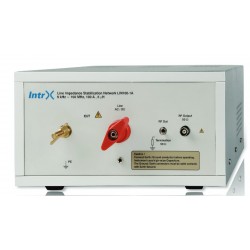
Intrx Single Path Automotive LISN for CISPR 25, ISO 7637 and BCI Testing
-
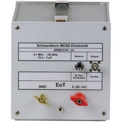
Schwarzbeck NNBM 8124 Single Path Vehicle AMN (LISN)
-
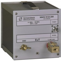
Schwarzbeck NNHV 8123-200 Single Path High Voltage AMN (LISN)
-
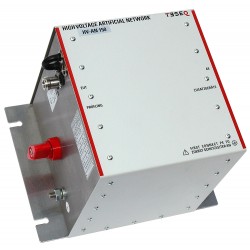
Teseq HV-AN 150 Artificial Network (AN) for Automotive, Airborne and MIL
-
Schwarzbeck NNHV 8123 Single Path High Voltage AMN (LISN)
-
Com-Power LI-3100 Line Impedance Stabilization Network
-
Com-Power LI-550A Line Impedance Stabilization Network (LISN)
-
Schwarzbeck NNHV 8123-800 Single Path High Voltage AMN (LISN)
-

Com-Power LI-550C 100 kHz to 108 MHz Line Impedance Stabilization Network
-
Schwarzbeck DC-Block 500 DC-Blocking Capacitor
-
Solar LISN 9117-5-TS-50N for CISPR 25, FCC Part 18 and More
-
LISN-CISPR25 Single Path Automotive Line Impedance Stabilization Network