No products
Product successfully added to your shopping cart
There are 0 items in your cart. There is 1 item in your cart.
EM Test Current Surge Testers
- EMC Test Equipment
- Transient Generators
- RF Power Amplifiers
- DC - 300 kHz RF Amplifiers
- 10 kHz - 250 MHz RF Amplifiers
- 10 kHz - 400 MHz RF Amplifiers
- 10 kHz - 1 GHz RF Amplifiers
- 80 MHz - 1 GHz RF Amplifiers
- 1 GHz - 2 GHz RF Amplifiers
- 700 MHz - 4.2 GHz RF Amplifiers
- 1 GHz - 6 GHz RF Amplifiers
- 2 GHz - 8 GHz RF Amplifiers
- 6 GHz - 18 GHz RF Amplifiers
- 18 GHz - 40 GHz RF Amplifiers
- Pulse Amplifiers
- RF Field Strength Probes & Meters
- RF Conducted Immunity
- EMC Receivers/EMI Analyzers
- EMC Antennas
- Coupling Decoupling Networks (CDN's)
- Line Impedance Stabilization Networks (LISN's)
- RF Test Equipment
- EMC Probes
- EMC Measurement & Equipment Software
- Power Supplies
- Electrical Safety Analyzers
- High Precision Laboratory Power Analyzers & Meters
- Anechoic Chambers
- Over-the-Air (OTA) Test Chambers
- EMI RF Shielded Tent Enclosures
- RF Shielded Rooms
- EMC Absorber
- Positioning Equipment
- EMC/EMI Test Setup
- GTEM Cells / TEM Cells
- Reverberation Chambers
- Used RF Anechoic Chambers
- EMC Chamber Filters
- EMC Chamber Shielding Gaskets
- RF Shielded Doors
- Anechoic Chamber Accessories
- Fully Anechoic (FAR) Test Chambers
- Manufacturers
- 3ctest
- AE Techron
- AH Systems
- Amplifier Research
- Boonton
- Com-Power
- Diamond Engineering
- EM Test (Ametek CTS)
- EMC Partner
- EMC Test Design
- Empower High Power RF Amplifiers
- ETS-lindgren
- Log Periodic Dipole Array Antenna
- Near Field Probe Sets
- Double Ridge Horn Antennas
- Biconical Antennas
- Quad Ridge Horn Antennas
- Electric Field Probes
- GTEM's
- Positioners & Tripods
- Loop Antennas
- Biconilog Antennas
- LISN's (Line Impedance Stabilization Network)
- Shielded Enclosures/Rooms
- Monopole Antennas
- Field Generating Antennas
- Fischer Custom Communications
- Haefely Hipotronics
- Haefely EFT/Burst Immunity Test Systems
- Haefely Surge Combination Wave Test Systems
- Haefely Surge Damped Oscillating Wave Test Systems
- Haefely Electrostatic Discharge Test Systems (ESD)
- Haefely Surge Ring Wave Test Systems
- Haefely Surge Telecom Wave Test Systems
- Haefely Magnetic Field Test Systems
- Haefely CDN's (Coupling/Decoupling Networks)
- IFI Amplifiers
- Keysight (Agilent)
- MVG - Microwave Vision Group
- PMM / Narda
- Rohde & Schwarz RF Test Equipment
- Rohde & Schwarz Broadband RF Amplifiers
- Rohde & Schwarz Spectrum Analyzers
- Rohde & Schwarz Compliant EMI Test Receivers
- Rohde & Schwarz Isotropic RF Probes
- Rohde & Schwarz RF Signal Generators
- Rohde & Schwarz RF Switches
- Rohde & Schwarz Oscilloscopes
- Rohde & Schwarz RF Power Meters
- Rohde & Schwarz RF Power Sensors
- Schloder
- Schwarzbeck Mess-Elektronik
- Schwarzbeck Antennas
- Schwarzbeck Automotive Antennas
- Schwarzbeck Broadband Horn Antennas
- Schwarzbeck Biconical Antennas
- Schwarzbeck Logarithmic Periodic Broadband Antennas
- Schwarzbeck Stacked Log-Periodic Broadband Antennas
- Schwarzbeck Biconic Log-Periodic Antennas
- Schwarzbeck Dipole Antennas
- Schwarzbeck Rod Antennas
- Schwarbeck Antenna Baluns / Holders
- Schwarzbeck LISN Line Impedance Stabilisation Networks
- Schwarbeck Decoupling & Absorbing Clamps
- Schwarzbeck Field Probes
- Schwarzbeck Helmholtz Coils
- Schwarzbeck Antenna Masts
- Schwarzbeck Coupling/Decoupling Networks
- Schwarzbeck Antennas
- Solar Electronics
- Teseq (Schaffner)
- Teseq Automotive Transient Generators
- Teseq RF Test Equipment
- Teseq EFT/Burst Generators
- Teseq RF Immunity Generators
- Teseq ESD Guns
- Teseq Surge Generators
- Teseq Harmonics & Flicker Solutions
- Teseq Dips, Interrupts & Variations Equipment
- Teseq Ring Wave Generators
- Teseq Oscillatory Waves Generators
- Teseq Absorbing Clamps / Ferrite Tube
- Teseq EMC Antennas
- Teseq Current Probes
- Teseq Coupling Networks
- Thermo Keytek
- Vicreate
- Compliance Standards
- International (IEC/EN)
- EN/IEC 61000-3-2
- EN/IEC 61000-3-3
- IEC 61000-3-11
- IEC / EN 610000-3-12
- EN/IEC 61000-4-2
- EN/IEC 61000-4-3
- EN/IEC 61000-4-4
- EN/IEC 61000-4-5
- EN/IEC 61000-4-6
- EN/IEC 61000-4-7
- EN/IEC 61000-4-8
- EN/IEC 61000-4-9
- EN/IEC 61000-4-10
- EN/IEC 61000-4-11
- EN/IEC 61000-4-12
- EN/IEC 61000-4-16
- EN/IEC 61000-4-18
- EN/IEC 61000-4-19
- EN/IEC 61000-4-20
- EN/IEC 61000-4-21
- EN/IEC 61000-4-29
- EN/IEC 61000-4-31
- IEC 61000-4-39
- EN/IEC 62132
- SEMI F47 Voltage Sag Immunity
- Product Standards
- Military & Aerospace Standards
- Automotive EMC Standards
- CISPR Standards
- Telecom Testing
- ANSI/IEEE Standards
- FCC Part 15
- FCC Part 30
- International (IEC/EN)
- Application/Test Type
- Radiated Immunity
- Bulk Current Injection Testing
- RF Emissions Testing
- Conducted Immunity
- Conducted Emissions
- Antenna Pattern Measurement
- CE Mark Testing
- Intentional Radiator Testing
- Pulsed HIRF Radar
- Over-the-Air (OTA) Testing
- 5G Test Solutions
- Automotive EMC
- SAR Measurement Equipment
- Radiated Emissions
- Battery Simulator Test Equipment
- Services
- Clearance
Viewed products
-

EM Test TSS 500 M2i...
10/1000 µs Current Surge Simulator...
 View larger
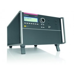
EM Test TSS 500 M2i Current Surge Simulator
New
- 10/1000 µs Current Surge Simulator
- Convenient DUT connection facilities
- A clearly arranged menu structure and;
- Display philosophy as well as the pre-programmed standard test routines;
- Make testing easy, reliable and safe
PDF Downloads
Test Equipment Description
EM Test TSS 500M2i is an intelligent solution offering exactly what you need for full-compliant immunity tests against transient surge phenomena. The distinct operation features, convenient DUT connection facilities, a clearly arranged menu structure and display philosophy as well as the pre-programmed standard test routines make testing easy, reliable and safe.
Operating Functions
Front Panel | |
 | |
| 1 | Display All functions and parameters are displayed (8 lines with max. 40 characters). | 7 | Escape When pressing the ESC button the user moves back one page in the menu. |
| 2 | "Test On" By pressing the key "Test On" the test procedure is initiated with the preselected parameters. The red LED indicates the trigger of a burst event. | 8 | CRO U ( surge) At the BNC output the residual voltage pulse across the supressor can be measured. Dividing ratio is 100:1 (5V at 500V pulse). |
| 3 | Function keys "F1..F7 Parameters and functions, displayed in the lowest line, can be selected with the related function key. | 9 | CRO I ( surge) At the BNC output the current pulse of the generator can be measured. Dividing ratio is 10:1 (5V at 50A pulse). |
| 4 | Knob (Inc / Dec) The knob increments or decrements test parameters with a numeric value or selects from a list of parameters. | 10 | CRO trigger output ↑ 5V At the BNC output the generator trigger pulse is available (+5 V rectangular). This output can be generally used as oscilloscope trigger output and is synchronous to the surge impulse |
| 5 | Cursor keys "←" and "→" Parameters and functions can be changed on-line. The selection of these parameters is realized with the cursor moving to the left or to the right. | 11 | HV output frontside (parallel to the output on the top) This HV output is in parallel to the output on the top of the TSS 500 M2i. This output can be used if the plugs on the frontside are more practically. |
| 6 | Exit Pressing of the Exit function will cause a reset of the firmware. This is only possible if no test routine is running. | 12 | HV output test box HV output on the Top cover for plug in the test adapter. |
Rear view | |
 | |
| 1 | SYNC input An ac voltage to which the events shall be synchronized is connected to this input. If no voltage is available the tests are started automatically in asynchronous mode. The maximum input voltage is 250VAC/400Hz. | 7 | Mains selector Selection 115/230V |
| 2 | Reference earth connection The generator has to be connected to the reference earth plane of the test set up. The connection at the rear part of the generator is an alternative to the grounding point at the front panel | 8 | The switch The switch is part of the mains filter. Mains fuses are part of the filter. |
| 3 | Ventilation After long term duration tests the generator should keep on running for some minutes to cool down the system. | 9 | Fuse F3 of the high voltage power supply The high voltage power supply unit is protected against overload by this fuse. In case that no pulses are generated anymore please check the fuse. |
| 4 | Warning lamp A control signal of (+24V/100mA) is available for external warning indications (warning lamp). The signal is generated after pressing TEST ON. | 10 | Serial interface RS232 interface with a 9 pin connector. |
| 5 | External trigger The test can only be started if the security circuit is closed. If the circuit is opened during a running test the simulator will be switched off immediately. | 11 | Parallel interface IEEE-488 interface with IEEE connector. |
| 6 | Exit One single surge pulse can be released. Trigger level 1-15V positive going. | 12 | Remote control connector External coupling devices are controlled via this remote control connector. |
| 13 | Fail detection FAIL 1 (TEST STOP) Fail detection FAIL 2 (TEST PAUSE) | ||
| Technical Data | ||
| SURGE Current Requirements as per Bellcore GR 1089 | ||
| Test level | ||
| Charging voltage | 50 – 1200V ± 10% step 10V | |
| Current Range I | 0 – 5A | |
| Current Range II | 1 – 15A | |
| Current Range III | 3 – 50A | |
| Short circuit current | Max. 50A | |
| Wave Shape | ||
| Front Time T1 (1.25 x tr) | 10µs -4µs / + 0µs | |
| Pulse duration T2 | 1000µs +500µs / - 0µs | |
| Polarity | Pos., Neg., Alt | |
| Repetition rate | 3s - 999s | |
| Events preselection | 1 - 30'000 or endless | |
| Counter | 1 - 1000000 | |
| Trigger | ||
| Trigger of pulses | AUTO, MAN, EXTERN | |
| Synchronization | 0 - 360° (16 - 500Hz) | |
| Resolution | 1° | |
| Output | ||
| Test box | Mounted on top of the generator | |
| Measurements | ||
| CRO | 5V Trigger | |
| CRO Û | 1V / 10V Only for measuring residual voltages up to 500V on VDR’s | |
| CRO Î | Range I 1V/A | |
| Peak voltmeter | Range II and III 100mV/A Peak voltmeter 500V | |
| Peak current meter | 50A | |
| Test Routines | ||
| Quick Start | Immediate start, all parameters adjustable during a running test | |
| User Test Routines | User specific test routines ( 7 stores each ) Change voltage level V after n pulses by ∆V Change phase angle A after n pulses by ∆A Change polarity after n pulses | |
| General Specifications | ||
| Power mains supply | 230V/115V, 50/60Hz, less than 75W | |
| Fuse | 230V : 2 AT slow blow 115V : 4 AT slow blow | |
| Safety | ||
| Safety circuit | External interlock capability | |
| Warning lamp | voltage free contact max. 250V 5A | |
| Design | per IEC 1010, EN 61010 | |
| Interfaces | ||
| Serial RS 232 | 1200 - 19200 Baud | |
| Parallel IEEE | Address 1-31 | |
| Dimensions | 19" / 6 HU 450 x515 x 290 mm ( Wx D x H ) | |
| Weight | app. 25 kg | |
| Environment | ||
| Temperature | 15° - 35° | |
| Humidity | max. 80% non condensing | |
| Test Box | ||
| Dimension | 120 x 87 x87 mm ( W x D x H ) Height 110 with connector | |
| Internal space for EUT | Clip device for SMD components | |
| Safety | Interlock with magnetic switch | |
| Weight | 0.38kg | |
Maintenance and service
General
The generator is absolutely maintenance-free by using a solid state semiconductor switch to generate transients.
Test set- up
When setting up the test national and international regulations regarding human safety have to be guaranteed.
It is recommended to connect the simulator to the ground reference plane of the test set-up.
Calibration and verification
Factory calibration
Every EM TEST generator is entirely checked and calibrated as per international standard regulations before delivery. A calibration certificate is issued and delivered along with a list of the equipment used for the calibration proving the traceability of the measuring equipment. All auxiliary equipment and accessories are checked to our internal manufacturer guidelines.
The calibration certificate and the certificate of compliance (if available) show the date of calibration. The EM Test equipment are calibrated in the factory and marked with a calibration mark. The used measuring instruments are traceable to the Swiss Federal Office of Metrology.
The calibration date is marked. The validity of the calibration is to the responsibility of the user’s quality system. Neither the certificate of calibration nor the corresponding label mark any due date for re-calibration.
Guideline to determine the calibration period of EM Test instrumentation
Our International Service Departments and our QA Manager are frequently asked about the calibration interval of EM TEST equipment. EM TEST doesn’t know each customer’s Quality Assurance Policy nor do we know how often the equipment is used and what kind of tests are performed during the life cycle of a test equipment. Only the customer knows all the details and therefore the customer needs to specify the calibration interval for his test equipment. In reply to all these questions we like to approach this issue as follows : EM TEST make use of a solid state semiconductor switch technique to generate high voltage transients. A precious advantage of this technique is the absolute lack of periodical maintenance effort. In consequence thereof a useful calibration period has to be defined based on two criteria:
- The first one is the customer’s Quality Assurance Policy. Any existent internal regulation has to be applied at highest priority. In the absence of such internal regulation the utilization rate of the test equipment has to be taken into consideration.
- Based on the experience and observation collected over the years EM TEST recommend a calibration interval of 1 year for frequently used equipment. A 2-years calibration interval is considered sufficient for rarely used test generators in order to assure proper performance and compliance to the standard specifications.
Calibration of Accessories made by passive components only:
Passive components do not change their technical specification during storage. Consequently the measured values and the plots stay valid throughout the storage time. The date of shipment shall be considered as the date of calibration.
Periodically In-house verification
Please refer to the corresponding standard before carrying out a calibration or verification. The standard describes the procedure, the tolerances and the the necessary auxiliary means. Suitable calibration adapters are needed. To compare the verification results, EM Test suggests to refer to the waveshape and values of the original calibration certificate.