No products
Product successfully added to your shopping cart
There are 0 items in your cart. There is 1 item in your cart.
Keysight (Agilent) RF Power Meters
- EMC Test Equipment
- Transient Generators
- RF Power Amplifiers
- DC - 300 kHz RF Amplifiers
- 10 kHz - 250 MHz RF Amplifiers
- 10 kHz - 400 MHz RF Amplifiers
- 10 kHz - 1 GHz RF Amplifiers
- 80 MHz - 1 GHz RF Amplifiers
- 1 GHz - 2 GHz RF Amplifiers
- 700 MHz - 4.2 GHz RF Amplifiers
- 1 GHz - 6 GHz RF Amplifiers
- 2 GHz - 8 GHz RF Amplifiers
- 6 GHz - 18 GHz RF Amplifiers
- 18 GHz - 40 GHz RF Amplifiers
- Pulse Amplifiers
- RF Field Strength Probes & Meters
- RF Conducted Immunity
- EMC Receivers/EMI Analyzers
- EMC Antennas
- Coupling Decoupling Networks (CDN's)
- Line Impedance Stabilization Networks (LISN's)
- RF Test Equipment
- EMC Probes
- EMC Measurement & Equipment Software
- Power Supplies
- Electrical Safety Analyzers
- High Precision Laboratory Power Analyzers & Meters
- Anechoic Chambers
- Over-the-Air (OTA) Test Chambers
- EMI RF Shielded Tent Enclosures
- RF Shielded Rooms
- EMC Absorber
- Positioning Equipment
- EMC/EMI Test Setup
- GTEM Cells / TEM Cells
- Reverberation Chambers
- Used RF Anechoic Chambers
- EMC Chamber Filters
- EMC Chamber Shielding Gaskets
- RF Shielded Doors
- Anechoic Chamber Accessories
- Fully Anechoic (FAR) Test Chambers
- Manufacturers
- 3ctest
- AE Techron
- AH Systems
- Amplifier Research
- Boonton
- Com-Power
- Diamond Engineering
- EM Test (Ametek CTS)
- EMC Partner
- EMC Test Design
- Empower High Power RF Amplifiers
- ETS-lindgren
- Log Periodic Dipole Array Antenna
- Near Field Probe Sets
- Double Ridge Horn Antennas
- Biconical Antennas
- Quad Ridge Horn Antennas
- Electric Field Probes
- GTEM's
- Positioners & Tripods
- Loop Antennas
- Biconilog Antennas
- LISN's (Line Impedance Stabilization Network)
- Shielded Enclosures/Rooms
- Monopole Antennas
- Field Generating Antennas
- Fischer Custom Communications
- Haefely Hipotronics
- Haefely EFT/Burst Immunity Test Systems
- Haefely Surge Combination Wave Test Systems
- Haefely Surge Damped Oscillating Wave Test Systems
- Haefely Electrostatic Discharge Test Systems (ESD)
- Haefely Surge Ring Wave Test Systems
- Haefely Surge Telecom Wave Test Systems
- Haefely Magnetic Field Test Systems
- Haefely CDN's (Coupling/Decoupling Networks)
- IFI Amplifiers
- Keysight (Agilent)
- MVG - Microwave Vision Group
- PMM / Narda
- Rohde & Schwarz RF Test Equipment
- Rohde & Schwarz Broadband RF Amplifiers
- Rohde & Schwarz Spectrum Analyzers
- Rohde & Schwarz Compliant EMI Test Receivers
- Rohde & Schwarz Isotropic RF Probes
- Rohde & Schwarz RF Signal Generators
- Rohde & Schwarz RF Switches
- Rohde & Schwarz Oscilloscopes
- Rohde & Schwarz RF Power Meters
- Rohde & Schwarz RF Power Sensors
- Schloder
- Schwarzbeck Mess-Elektronik
- Schwarzbeck Antennas
- Schwarzbeck Automotive Antennas
- Schwarzbeck Broadband Horn Antennas
- Schwarzbeck Biconical Antennas
- Schwarzbeck Logarithmic Periodic Broadband Antennas
- Schwarzbeck Stacked Log-Periodic Broadband Antennas
- Schwarzbeck Biconic Log-Periodic Antennas
- Schwarzbeck Dipole Antennas
- Schwarzbeck Rod Antennas
- Schwarbeck Antenna Baluns / Holders
- Schwarzbeck LISN Line Impedance Stabilisation Networks
- Schwarbeck Decoupling & Absorbing Clamps
- Schwarzbeck Field Probes
- Schwarzbeck Helmholtz Coils
- Schwarzbeck Antenna Masts
- Schwarzbeck Coupling/Decoupling Networks
- Schwarzbeck Antennas
- Solar Electronics
- Teseq (Schaffner)
- Teseq Automotive Transient Generators
- Teseq RF Test Equipment
- Teseq EFT/Burst Generators
- Teseq RF Immunity Generators
- Teseq ESD Guns
- Teseq Surge Generators
- Teseq Harmonics & Flicker Solutions
- Teseq Dips, Interrupts & Variations Equipment
- Teseq Ring Wave Generators
- Teseq Oscillatory Waves Generators
- Teseq Absorbing Clamps / Ferrite Tube
- Teseq EMC Antennas
- Teseq Current Probes
- Teseq Coupling Networks
- Thermo Keytek
- Vicreate
- Compliance Standards
- International (IEC/EN)
- EN/IEC 61000-3-2
- EN/IEC 61000-3-3
- IEC 61000-3-11
- IEC / EN 610000-3-12
- EN/IEC 61000-4-2
- EN/IEC 61000-4-3
- EN/IEC 61000-4-4
- EN/IEC 61000-4-5
- EN/IEC 61000-4-6
- EN/IEC 61000-4-7
- EN/IEC 61000-4-8
- EN/IEC 61000-4-9
- EN/IEC 61000-4-10
- EN/IEC 61000-4-11
- EN/IEC 61000-4-12
- EN/IEC 61000-4-16
- EN/IEC 61000-4-18
- EN/IEC 61000-4-19
- EN/IEC 61000-4-20
- EN/IEC 61000-4-21
- EN/IEC 61000-4-29
- EN/IEC 61000-4-31
- IEC 61000-4-39
- EN/IEC 62132
- SEMI F47 Voltage Sag Immunity
- Product Standards
- Military & Aerospace Standards
- Automotive EMC Standards
- CISPR Standards
- Telecom Testing
- ANSI/IEEE Standards
- FCC Part 15
- FCC Part 30
- International (IEC/EN)
- Application/Test Type
- Radiated Immunity
- Bulk Current Injection Testing
- RF Emissions Testing
- Conducted Immunity
- Conducted Emissions
- Antenna Pattern Measurement
- CE Mark Testing
- Intentional Radiator Testing
- Pulsed HIRF Radar
- Over-the-Air (OTA) Testing
- 5G Test Solutions
- Automotive EMC
- SAR Measurement Equipment
- Radiated Emissions
- Battery Simulator Test Equipment
- Services
- Clearance
Viewed products
-

Keysight N1912A...
30 MHz Video Bandwidth Single shot...
 View larger

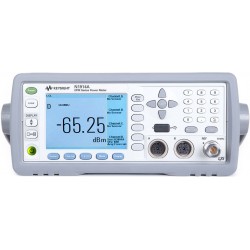
Keysight N1912A P-Series Dual Channel Power Meter
Used
- 30 MHz Video Bandwidth
- Single shot real time capture at 100 Msample/s per second
- Key Measurements: - peak, average, peak-to-average ratio, rise time, fall time and pulse width
- 22 Predefined formats: WiMAX, DME, HSDPA, etc.
- One screen view for pulse measurement analysis: Auto Scale, Auto Gate, Rise/Fall Time, Duty Cycle, etc.
- Internal Zeroing and Calibration while connecting to the DUT
- BenchVue software enabled
PDF Downloads
Data Sheet
N1911A/N1912A P-Series Power Meters and N1921A/N1922A Wideband Power Sensors
PDF Downloads (1.38M)Technical Overview
Seven Practices to Prevent Damaging Power Meters and Power Sensors
PDF Downloads (1.97M)Test Equipment Description
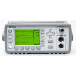
Keysight N1914A EPM Series Power Meters

A winning combination of Bandwidth and Performance
- LXI Class-C compliance with built-in Ethernet
- 30 MHz video bandwidth
- Single-shot real time and repetitive capture at 100 M-samples/s
- Zero and calibrate while still connected to the DUT
- Peak, average, and peak-to-average ratio power measurements plus rise time, fall time, pulse width, time to positive occurrence and time to negative occurrence time measurements
- 22 presets for WiMAXTM and DME measurements
- Conigurable reference level for rise and fall time measurement
Designed For Today’s Demanding Applications
Today’s complex electronic devices have stringent power requirements. Keysight Technologies, Inc. P-Series power meters and sensors deliver the wide bandwidth and high performance measurements that you need to be conident that your products are meeting their power speciications. The P-Series power meters have a 30 MHz video bandwidth and 100 M-sample/s continuous sampling rate for fast, accurate, and repeatable power measurements. When these meters are used with the P-Series wideband power sensors, they provide up to 40 GHz frequency coverage, wide dynamic range, and extensive measurement capability that has been optimized for aerospace/defense, wireless communication, and wireless networking (IEEE 802.11a/b/g) applications.
The P-Series power meters is now LXI (LAN eXtensions for Instrumentation) Class-C compliant instrument which combines the advantages of Ethernet with simplicity and familiarity of GPIB. This helps the test systems designers and integrators to create a faster and more eficient systems. With the power of ethernet, the P-Series power meters reduces the time needed to setup, conigure and debug test systems.
Packed with capability
When you choose the P-Series power meters and sensors, you get best-in-class pulse analysis and peak power measurement speciications.
A high-performance, 14-bit, 100 M-sample/s measurement engine drives the P-Series power meters, so you can capture single-shot as well as repetitive events over a wide bandwidth. For applications such as radar testing that require accurate pulse measurements, the power meter and sensor combination has ≤ 13 ns warranted rise and fall time performance.
With up to 30 MHz of video bandwidth, the P-Series gives you a single-instrument solution for testing wide bandwidth products such as the multi-carrier power ampliiers used in the newest wireless base stations.
Bandwidth latness is corrected to 0.1 dB over the 30 MHz bandwidth for highly accurate peak power measurements.
Comprehensive power, time, and statistical measurements1
The P-Series power meters and sensors offer comprehensive measurements that satisfy the requirements of many power applications in R&D and manufacturing.
– Peak power, min power, average power, and peak-to- average ratio power measurements
– Time-gated and free-run measurement modes
– Automatic rise time, fall time, pulse width, pulse period, duty cycle, time to positive occurrence, and time to negative occurrence time measurements
– Auto scale and auto gate of pulse
– Complementary cumulative distribution function (CCDF) statistics
PC-based measurement software (N1918A)2 adds even more pulse-parameter and statistical analysis capability, for performance approaching that of a traditional peak power analyzer.
Flexible Configurations
With the P-Series products, you can choose a coniguration that’s right for your application:
P-Series Power Meters
N1911A single-channel power meter,
9 kHz to 110 GHz (sensor-dependent)
N1912A dual-channel power meter,
9 kHz to 110 GHz (sensor-dependent)
P-Series power sensors
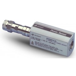
N1921A wideband power sensor, 50 MHz to 18 GHz
N1922A wideband power sensor, 50 MHz to 40 GHz
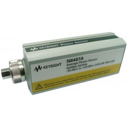
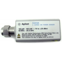
The P-Series power meters are also compatible with all 8480 Series, E-Series and N8480 Series sensors.
External Calibration-Free Measurements
The P-Series power sensors are the irst to provide “internal zero and calibration” which eliminates the need for sensor calibration using an external reference source. Keysight’s patent-pending technology (see Figure 1) integrates a dc reference source and switching circuits into each power sensor, so that you can zero and calibrate the sensor while it is connected to a device under test. This feature removes the need for connection and disconnection from the calibra- tion source, thereby reducing test times, measurement un- certainty, and wear and tear on connectors. It is especially useful in manufacturing and automated test environments where every second and every connection counts. Sensors can be embedded within test ixtures without the need to switch in reference signals.
Simpliied Correction Factors
To ensure the accuracy of power measurements, a power meter typically overlays many different sensor correction factors including linearity, frequency, and temperature. At higher bandwidths, this technique can become cumbersome and less than accurate.

Figure 1. Internal zero and cal block diagram
To simplify the process and improve measurement speed while preserving measurement accuracy, the P-Series uses a four-dimensional (4-D) modeling technique that measures input power, frequency, temperature, and output voltage across the power sensor’s speciied measurement ranges. Data from this 4-D model is generated during Keysight’s ini- tial factory calibration of the sensor and stored in EEPROM. Advanced algorithms are used to quickly and accurately evaluate the sensors against this model, without requiring the power meter to interpolate the calibration factors and linearity curves. If you run tests in which the frequency changes often, e.g. testing multi-carrier ampliiers on different bands, you’ll notice a marked improvement in measurement speed.
Compatibility with more than 30 Keysight sensors
The P-Series power meters also work with the Keysight 8480 Series, E-Series and N8480 Series power sensors. This gives you a selection of more than 30 sensors for power measurements over a wide dynamic range from –70 to +44 dBm, with frequency coverage of 9 kHz to 110 GHz.
Designed for Test Standardization and Interoperability
The P-Series power meters enables fast, eficient and cost effective creation. It also enables re-coniguration of test system with proven and widely used standards such as Ethernet, Web browsers and IVI drivers. The codes are transferable/reusable from design and development industry to manufacturing. Best of all, the same test system software can be leveraged across industries such as Research and Development (R&D), design validation, manufacturing and services. By using the same software, test development time can be cut down signiicantly for new products to be marketed earlier. It also helps to provide more consistent results from development to production and prevent time wasted in correlating measurements results and inding the cause of differences. The use of industry standard drivers such as IVI drivers enables user to use any programming languages that they are familiar with. Therefore, it is hassle- free and effective when P-Series power meters is used during instrument communications.
Enable Remote Control/Access of the Instrument
Set up of power meter is possible through an informative instrument page where you can access with a standard web browser. This page contains key information such as the manufacturer, model number, serial number, description, hostname, a MAC address and IP address. Hence, you are able to change the parameters by typing the instrument’s IP address in the Web browser. Access of test data is also possible with the power meter built-in front panel.

Figure 2. Instrument web page browser
that provides instruments setting
at a glance and enable remote access/control

Figure 3. Web page browser—View and Modify LAN Configuration
Simpliied test set up
The P-Series meters are loaded with time saving features. Predefined test setups for common measurements (see Figure 2) used in radar and wireless communication applications get you started testing, and an easy-to-use menu structure lets you step quickly through measurement sequences.

Figure 4. Predefined Test Setups
Once you have started measuring, it’s easier to ine-tune, and save the setup for your unique requirements.
With an auto-pulse detect1 capability, the power meter can automatically trigger from an unknown input signal to display the entire pulse envelope and you’re ready to begin making measurements.
Internal triggering is exceptionally stable in the P-Series meters. Versatile time-gating features include four indepen- dent measurement gates. An external triggering capability lets you synchronize your measurements to an external signal, so the power meters can adapt to a wide range of input signal levels to accommodate many different types of incoming signals.
The high resolution, color display has a graphical user interface with multiple markers and marker functions for easy manual measurements. An IVI-COM driver for the P-Series power meters and sensors facilitates programming in Keysight VEE, LabView, Labwindows, C, C++, and MATLAB environments.
Convenience and security
Keysight’s IO Libraries Suite ships with the P-Series power meters to help you quickly establish an error-free connection between your PC and instruments regardless of the vendor. It provides robust instrument control and works with the software development environment you choose.
LAN, USB, and GPIB connectivity are standard in every P-Series power meter to accommodate the majority of modern interfaces.
Backwards compatibility of the P-Series meters with Keysight's current offering of power sensors gives you numerous options for extending the usefulness of your Keysight power measurement tools. Identical features and measurements performed by the EPM, EPM-P and P-Series power meters are code compatible, having the same SCPI commands.
A 2-year calibration cycle on the P-Series power meters helps reduce the cost of ownership. A universal line input lets you plug into a supply voltage just about anywhere without any additional hardware or adjustments, and multiple sensor cable length options (1.5 m, 3 m, and 10 m) make it easy to reach out-of-the-way devices in a variety of test environments.
Save your display information using a PC and SCPI commands. Screen dumps can be downloaded to a PC in the form of a bit-map. Power versus time trace displays can also be downloaded for further processing or for hardcopy printouts for your log book or your company literature.
Secure mode protects sensitive data by erasing from instrument memory all user parameters, including save/ recall states and power on last states.
Optimized for Radar Testing
| If you design or manufacture components and subcompo- nents for radar systems, you need a way to accurately mea- sure the output power and timing parameters of the radar pulses. The P-Series power meters and sensors provide a cost-effective peak and average power solution that is ideal for the task. With warranted performance that includes up to 40 GHz frequency range, a 30 MHz bandwidth and ≤ 13 ns rise and fall time, the P-Series covers most of today’s high frequency radar test applications. |

Ideal in the Lab and Manufacturing
In the lab or on the manufacturing loor, you can use the P-Series power meters and sensors to check that pulses in radar transmit or receive modules conform to a speciied amplitude and shape. You can focus your measurements on a single pulse or on a train of hundreds or even thousands of pulses. Use real-time markers and other features to help you determine whether the pulse power is degrading or the pulse shape is changing over time.
|
|
Figure 5. Markers 1 and 2 time and power, with Δ time and power measurements between markers. | Figure 6. Comprehensive time measurements: comprising rise time, fall time, pulse width, pulse period, duty cycle, time to positive and negative occurrences and pulse repetitive frequency. |


Comprehensive measurements are built in: peak, average, peak-to-average ratio, time and instantaneous power at markers 1 and 2 (see Figure 3), time measurements comprising rise time, fall time, pulse width, pulse period, duty cycle, time to positive occurrence, time to negative occurrence and pulse repetitive frequency (see Figure 4). While the power meter and sensor combination makes an excellent standalone power measurement system, the drivers included in the system make it easy to integrate into other systems in an ATE environment.
Measure the time delay between your trigger event and the pulse envelope
Automatic measurement of the time to positive occurrence allows you to verify the delay time between the trigger event using the pulse modulator to drive the power meter’s external trigger and the RF output of your transmitter.
Remote capture of up to 10 pulses
For ATE applications, using SCPI commands, you can automatically measure the important time parameters of pulse duration, separation and period on a capture of up to 10 pulses.
Alternative to a peak power analysis system
By providing comprehensive, accurate, and repeatable power measurements in a small form factor that is well- suited for R&D and manufacturing test, the P-Series power meters and sensors are a viable alternative to a peak power analysis system and at an attractive price point.
Optimized for Multi-channel Power Amplifier (MCPA) Testing
| The base stations that support today’s high capacity wireless networks must handle a growing number of data channels. Rather than incorporate a separate ampliier for each channel in the system, engineers are streamlining their designs by using multi-channel power ampliiers (MCPAs). If you are designing or manufacturing MCPAs, you need a wide bandwidth tool that can measure the peak and average power or peak-to-average ratio to verify that your product does not exceed maximum power speciications. The P-Series power meters and sensors offer a complete power measurement solution with a 30 MHz bandwidth. It can measure peak and average power of up to six 3G (5 MHz) carriers over a wide –35 to +20 dBm dynamic range, more than enough for power ampliier testing today and in the future. |

Accurate Power Measurements
The accuracy of power measurements is a major concern in high data rate wireless applications. With the P-Series products, you can accurately measure the linearity of power ampliiers (input power versus output power) at the 1 dB compression point.
The P-Series lat video bandwidth helps to ensure the accuracy of your peak and peak-to-average ratio power measurements. Keysight characterizes the P-Series sensors over their speciied temperature, frequency and power ranges. These correction factors are stored in EEPROM, so that along with an average power measurement accuracy speciication of ≤ ±0.2 dB (refer to Data Sheet 5989-2471EN) you don’t have to worry about the affects of error on your measurement.
Multi-level, TDMA Power Testing Made Easy
The P-Series power meters provide four independent time gates (A1-A4) in a single measurement setup (see Figure 5) so you can choose where you locate your measurements of peak, average, and peak-to-average ratio on the trace.

Figure 7. Measurement Flexibility with 4 Independent Time Gates
Optimized for Wireless LAN Testing
| If you are designing wireless LAN (IEEE 802.11a/b/g) or WiMAX (802.16e) components and subsystems, you will need to analyze bursted signals. With 30 MHz of video bandwidth, the P-Series power meters and sensors can capture signal bursts and measure the peak-to-average ratio of the transmitted power in your WLAN or WiMAX products. You can verify the power proile and output power of WLAN components easily with the P-Series solution. For example, because the length of a wireless LAN burst is unpredictable, it is affected by the type of data being transmitted and the data rates you are trying to achieve. |

By measuring the signal’s rise time and checking the burst proile, you can identify any power transitions that could cause interoperability problems. Measuring the peak-to- average ratio and CCDF enable you to verify that a power ampliier isn’t clipping.
The preconigured presets for WLAN and WiMAX allow easier capture of burst signals so you can get started on your measurements sooner.
|
|
Figure 8. WiMAX burst signal capture | Figure 9. CCDF statistical measurements |


Versatile for R&D and manufacturing
The P-Series power meters and sensors can measure all IEEE 802.11 WLAN signals. They can be used in developing HiperLAN and HomeRF network devices as well.
In component manufacturing, time is always money. This is true in the high volume production of wireless network devices and products where fast measurement speed is essential to maximize throughput. Minutes can be shaved from overall test times by combining the internal zero and calibration capability with the fast measurement speeds achieved through your choice of I/O interface (LAN, USB, and GPIB) for data transfer.
Capable and Easy-to-Use

A - | Half-rack width, 2 U height makes this instrument ideally sized for automated test environments. |
B - | Large, high-resolution color LCD has back-lighting that provides a wide angle for viewing the displayed data. |
C - | Full-screen graphical display has three display modes: power versus time, numeric readout, and pseudo-analog display. |
D - | Display keys let you select the display format for the active window, either single or split screen formats. Two horizontal windows show the trace display (power versus time) in several formats, a large 1- or 4-line numeric display or an analog display. |
E - | Hardkeys provide access to the most frequently used functions, such as Trigger and Acquisition |
F - | Softkey menus have been simpliied so that you can more readily conigure the meter to meet your speciic measurement needs. |
G - | Arrow keys and Select allow positioning of the cursor for character selection and editing. |
H - | Numeric keypad makes data entry easier. |
I - | 0 dBm, 50 MHz power reference connector is used for power sensor calibration traceable to national standards. Typically the power meter’s 0 dBm, 50 MHz reference is used to calibrate the 8480 Series, E-Series or N8480 Series sensors when they are used with the P-Series meters. (The P-Series sensors have internal zero and calibration and thus do not require calibration with the reference source.) |
J - | Cal enables fully automatic digital zeroing, corrected for residual offsets and fully automatic sensor calibration. |
K - | Run/Stop enables single-shot measurements. |
L - | Sensor connectors for attaching the P-Series sensor dual coaxial cables allow the P-Series power meters and sensors to achieve the best wideband speciications. Adapter cables N1917A/B/C are used to connect the 8480 Series, E-Series and N8480 Series power sensors to the P-Series power meter. |
Rear-Panel Features

| – | SB 2.0, Ethernet (LAN), and GPIB connections are standard. |
| – | Rear-panel sensor and 0 dBm Power Ref connectors, replacing the front-panel connectors, are an option (option 003) that makes it easy to incorporate the P-Series meters into a rack for automated testing. |
| – | Trig In accepts a TTL signal for initiating measurements. |
| – | Trig Out outputs a TTL signal for synchronizing with external equipment. |
| – | DC Recorder output, 0 to 1 volt. The N1912A has two recorder outputs as shown. |
| – | Ground connector is available for those applications that require a hard-wired connection between the power meter’s ground and a common ground. |
| – | Line power is provided by a universal input voltage range. |