
No products
Product successfully added to your shopping cart
There are 0 items in your cart. There is 1 item in your cart.
Programmable DC Power Supplies
- EMC Test Equipment
- Transient Generators
- RF Power Amplifiers
- DC - 300 kHz RF Amplifiers
- 10 kHz - 250 MHz RF Amplifiers
- 10 kHz - 400 MHz RF Amplifiers
- 10 kHz - 1 GHz RF Amplifiers
- 80 MHz - 1 GHz RF Amplifiers
- 1 GHz - 2 GHz RF Amplifiers
- 700 MHz - 4.2 GHz RF Amplifiers
- 1 GHz - 6 GHz RF Amplifiers
- 2 GHz - 8 GHz RF Amplifiers
- 6 GHz - 18 GHz RF Amplifiers
- 18 GHz - 40 GHz RF Amplifiers
- Pulse Amplifiers
- RF Field Strength Probes & Meters
- RF Conducted Immunity
- EMC Receivers/EMI Analyzers
- EMC Antennas
- Coupling Decoupling Networks (CDN's)
- Line Impedance Stabilization Networks (LISN's)
- RF Test Equipment
- EMC Probes
- EMC Measurement & Equipment Software
- Power Supplies
- Electrical Safety Analyzers
- High Precision Laboratory Power Analyzers & Meters
- Anechoic Chambers
- Over-the-Air (OTA) Test Chambers
- EMI RF Shielded Tent Enclosures
- RF Shielded Rooms
- EMC Absorber
- Positioning Equipment
- EMC/EMI Test Setup
- GTEM Cells / TEM Cells
- Reverberation Chambers
- Used RF Anechoic Chambers
- EMC Chamber Filters
- EMC Chamber Shielding Gaskets
- RF Shielded Doors
- Anechoic Chamber Accessories
- Fully Anechoic (FAR) Test Chambers
- Manufacturers
- 3ctest
- AE Techron
- AH Systems
- Amplifier Research
- Boonton
- Com-Power
- Diamond Engineering
- EM Test (Ametek CTS)
- EMC Partner
- EMC Test Design
- Empower High Power RF Amplifiers
- ETS-lindgren
- Log Periodic Dipole Array Antenna
- Near Field Probe Sets
- Double Ridge Horn Antennas
- Biconical Antennas
- Quad Ridge Horn Antennas
- Electric Field Probes
- GTEM's
- Positioners & Tripods
- Loop Antennas
- Biconilog Antennas
- LISN's (Line Impedance Stabilization Network)
- Shielded Enclosures/Rooms
- Monopole Antennas
- Field Generating Antennas
- Fischer Custom Communications
- Haefely Hipotronics
- Haefely EFT/Burst Immunity Test Systems
- Haefely Surge Combination Wave Test Systems
- Haefely Surge Damped Oscillating Wave Test Systems
- Haefely Electrostatic Discharge Test Systems (ESD)
- Haefely Surge Ring Wave Test Systems
- Haefely Surge Telecom Wave Test Systems
- Haefely Magnetic Field Test Systems
- Haefely CDN's (Coupling/Decoupling Networks)
- IFI Amplifiers
- Keysight (Agilent)
- MVG - Microwave Vision Group
- PMM / Narda
- Rohde & Schwarz RF Test Equipment
- Rohde & Schwarz Broadband RF Amplifiers
- Rohde & Schwarz Spectrum Analyzers
- Rohde & Schwarz Compliant EMI Test Receivers
- Rohde & Schwarz Isotropic RF Probes
- Rohde & Schwarz RF Signal Generators
- Rohde & Schwarz RF Switches
- Rohde & Schwarz Oscilloscopes
- Rohde & Schwarz RF Power Meters
- Rohde & Schwarz RF Power Sensors
- Schloder
- Schwarzbeck Mess-Elektronik
- Schwarzbeck Antennas
- Schwarzbeck Automotive Antennas
- Schwarzbeck Broadband Horn Antennas
- Schwarzbeck Biconical Antennas
- Schwarzbeck Logarithmic Periodic Broadband Antennas
- Schwarzbeck Stacked Log-Periodic Broadband Antennas
- Schwarzbeck Biconic Log-Periodic Antennas
- Schwarzbeck Dipole Antennas
- Schwarzbeck Rod Antennas
- Schwarbeck Antenna Baluns / Holders
- Schwarzbeck LISN Line Impedance Stabilisation Networks
- Schwarbeck Decoupling & Absorbing Clamps
- Schwarzbeck Field Probes
- Schwarzbeck Helmholtz Coils
- Schwarzbeck Antenna Masts
- Schwarzbeck Coupling/Decoupling Networks
- Schwarzbeck Antennas
- Solar Electronics
- Teseq (Schaffner)
- Teseq Automotive Transient Generators
- Teseq RF Test Equipment
- Teseq EFT/Burst Generators
- Teseq RF Immunity Generators
- Teseq ESD Guns
- Teseq Surge Generators
- Teseq Harmonics & Flicker Solutions
- Teseq Dips, Interrupts & Variations Equipment
- Teseq Ring Wave Generators
- Teseq Oscillatory Waves Generators
- Teseq Absorbing Clamps / Ferrite Tube
- Teseq EMC Antennas
- Teseq Current Probes
- Teseq Coupling Networks
- Thermo Keytek
- Vicreate
- Compliance Standards
- International (IEC/EN)
- EN/IEC 61000-3-2
- EN/IEC 61000-3-3
- IEC 61000-3-11
- IEC / EN 610000-3-12
- EN/IEC 61000-4-2
- EN/IEC 61000-4-3
- EN/IEC 61000-4-4
- EN/IEC 61000-4-5
- EN/IEC 61000-4-6
- EN/IEC 61000-4-7
- EN/IEC 61000-4-8
- EN/IEC 61000-4-9
- EN/IEC 61000-4-10
- EN/IEC 61000-4-11
- EN/IEC 61000-4-12
- EN/IEC 61000-4-16
- EN/IEC 61000-4-18
- EN/IEC 61000-4-19
- EN/IEC 61000-4-20
- EN/IEC 61000-4-21
- EN/IEC 61000-4-29
- EN/IEC 61000-4-31
- IEC 61000-4-39
- EN/IEC 62132
- SEMI F47 Voltage Sag Immunity
- Product Standards
- Military & Aerospace Standards
- Automotive EMC Standards
- CISPR Standards
- Telecom Testing
- ANSI/IEEE Standards
- FCC Part 15
- FCC Part 30
- International (IEC/EN)
- Application/Test Type
- Radiated Immunity
- Bulk Current Injection Testing
- RF Emissions Testing
- Conducted Immunity
- Conducted Emissions
- Antenna Pattern Measurement
- CE Mark Testing
- Intentional Radiator Testing
- Pulsed HIRF Radar
- Over-the-Air (OTA) Testing
- 5G Test Solutions
- Automotive EMC
- SAR Measurement Equipment
- Radiated Emissions
- Battery Simulator Test Equipment
- Services
- Clearance
Viewed products
-

DC1500-30 Programmable...
1500 V Rated voltage & range...
-

Teseq CDN 500...
Coupling Clamp for signal lines...
 View larger
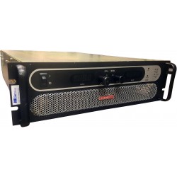
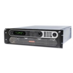
DC1500-30 Programmable High Efficiency DC Power Supply 1500 V
New
- 1500 V Rated voltage & range
- Multi-phase input for 400 V AC or 208 V AC (US models)
- High efficiency up to 95.5%
- Output power ratings: 3.3 kW, 5 kW, 6.6 kW, 10 kW or 15 kW, expandable up to 480 kW
- Output voltages: 40 V up to 1500 V
- Output currents: 30 A up to 510 A, expandable up to 5100 A
- Flexible, power regulated output stage
- Various protection circuits (OVP, OCP, OPP, OTP)
- Intuitive TFT touch panel with display for values, status and notifications
- Remote sensing with automatic detection
- Galvanically isolated, analog interface
- Integrated true function generator
- Photovoltaic array simulation
- Internal resistance simulation and regulation
- 40 V models compliant to SELV (EN 60950)
- Discharge circuit (Uout < 60 V in ≤ 10 s)
- USB port integrated
- EMC TÜV approved for EN 61010 Class B
- Optional, digital interface modules or alternatively installed IEEE/GPIB port
- SCPI command language supported
Test Equipment Description
The microprocessor controlled high efficiency laboratory power supplies of series EA-PSI 9000 3U offer multiple functions and features in their stand- ard version. User-friendly, interactive menu navigation makes the use of this equipment remarkably easy and most effective. User and process profiles can be edited, saved and archived so that the re- producibility of a test or other application is improved. In order to achieve even higher output power, cabinets with up to 150 kW and up to 42U size can be configured to suit the user‘s requirements.
AC input
All models are provided with an active Power Factor Correction circuit and are designed for a usage on a three-phase supply with 340 V up to 460 V AC (european models) or 188 V up to 229 V AC (US models).
Auto-ranging power stage
All models are equipped with a flexible auto-ranging out- put stage which provides a higher output voltage at lower output current, or a higher output current at lower output voltage, always limited to the max. nominal output power. The power set value is adjustable with these models.
Therefore, a wide range of applications can already be covered by the use of just one unit.
DC output
DC output voltages between 0...40 V and 0...1500 V, output currents between 0...40 A and 0...510 A and output power ratings of 0...3.3 kW, 0...5 kW, 0...6.6 kW, 0...10 kW or 0...15 kW are available. The DC output terminal is located on the rear panel.
Discharge circuit
Models with a nominal output voltage of 200 V or higher include a discharge circuit for the output capacities. For no load or low load situations, it ensures that the dangerous output voltage can sink to under 60 V DC after the DC output has been switched off. This value is considered as limit for voltages dangerous to human safety.
Protective features
For protection of the equipment connected, it is possible to set an over voltage protection threshold (OVP), as well as one for over current (OCP) and overpower (OPP). As soon as one of these thresholds is reached for any reason, the DC output will be immediately shut off and a status signal will be generated on the display and via the interfaces. There is furthermore an over temperature protection, which will shut off the DC output if the device overheats.
Remote sensing
The standard sensing input can be connected directly to the load in order to compensate voltage drops along the power cables up to a certain level. If the sensing input is connected to the load, the power supply will adjust the output voltage automatically to make ensure the accurate required voltage is available at the load.
Analog interface
There is a galvanically isolated analog interface terminal, located on the rear of the device. It offers analog in- puts to set voltage, current, power and resistance from 0...100% through control voltages of 0 V...10 V or 0 V...5 V.
To monitor the output voltage and current, there are analog outputs with 0 V...10 V or 0 V...5 V. Also, several inputs and outputs are available for controlling and monitoring the device status.
Display and control panel

Set values and actual values of output voltage, output current and output power are clearly represented on the graphic display. The colour TFT screen is touch sensitive and can be intuitively used to control all functions of the device with just a finger. Set values of voltage, current, power or resistance (internal resistance simulation) can be adjusted using the rotary knobs or entered directly via a numeric pad.
To prevent unintentional operations, all operation controls can be locked.
Multi-language control panel
 |  |
Function generator
All models within this series include a true function generator which can generate typical functions, as displayed in the figure below, and apply them to either the output voltage or the output current. The generator can be completely configured and controlled by using the touch panel on the front of the device, or by remote control via one of the digital interfaces. The predefined functions offer all necessary parameters to the user, such as Y offset, time / frequency or amplitude, for full configuration ability.

Additionally to the standard functions, which are all based upon a so-called arbitrary generator, this base generator is accessible for the creation and execution of complex sets of functions, separated into up to 99 sequences. Those can be used for testing purposes in development and production. The sequences can be loaded from and saved to a standard USB flash drive via the USB port on the front panel, making it easy to change between different test sequences.
There is furthermore a XY generator, which is used to generate other functions, such as UI or IU, which are definned by the user in form of tables (CSV file) and then loaded from USB drive. For photovoltaics related tests, a PV curve can be generated and used from user-adjustable key parameters. Even more characteristics can be installed for user selection by applying future firmware updates.
Master-slave
All models feature a digital master-slave bus by default. It can be used to connect up to 32 units of identical models in parallel operation to a bigger system with totals formation of the actual value of voltage, current and power. The configuration of the master-slave system is either completely done on the control panels of the units or by remote control via any of digital communication interfaces. Handling of the master unit is possibly by manual or remote control (any interface). Alternatively to the standard models, there are specific slave models available. See page 35.
Control software 
Included with the device is a control software for Windows PC, which allows for the remote control of multiple identical or even different types of devices.
It has a clear interface for all set and actual values, a direct input mode for SCPI and ModBus RTU commands, firmware update feature and the semi-automatic table control named “Sequencing”.
Options
- Digital interface modules for RS232, CAN, CANopen, ModBus TCP, Profibus, Profinet/IO, EtherCAT or Ethernet. Pluggable, retrofittable, simple installation and setup.
- Three-way interface (3W) with a rigid GPIB port installed instead of the default slot for retrofittable interface modules
- High Speed ramping
- Water cooling

| Technical Data | |
| AC Supply | |
| Voltage | European models: 340...460 V, 2ph/3ph US models: 188...229 V, 2ph/3ph |
| Frequency | 45...66 Hz |
| Power factor | >0.99 |
| DC Voltage | |
| Accuracy | <0.1% of rated value |
| Load regulation 0-100% | <0.05% of rated value |
| Line regulation ±10% U AC | <0.02% of rated value |
| Regulation 10-100% load | |
| Slew rate 10-90% | Max. 30 ms |
| Over voltage protection | Adjustable, 0...110% U Nom |
| No load discharge time on DC off | 100% U auf / to |
| DC Current | |
| Accuracy | <0.2% of rating |
| Load regulation 0-100% U DC | <0.15% of rated value |
| Line regulation ±10% U AC | <0.05% of rated value |
| DC Power | |
| Accuracy | <1% of rated value |
| Over voltage category | 2 |
| Protection | OT, OVP, OCP, OPP, PF (2 |
| Insulation 1 | |
| AC input to enclosure | 2500 V DC |
| AC input to DC output | 2500 V DC |
| DC output to enclosure (PE) | Depending on model |
| Degree of pollution | 2 |
| Protection class | 1 |
| Display and panel | Graphics display with touch panel |
| Digital interfaces | |
| Built-in | 1x GPIB (optional mit Option 3W) / 1x GPIB (optional with option 3W) |
| Slot | 1x for retrfittable plug-in modules (standard models only) |
| Analog interface | Built-in, 15 pole D-Sub (female), galvanically isolated |
| Signal range | 0...5 V or 0...10 V (switchable) |
| Inputs | U, I, P, R, remote control on-ff, DC output on-off, resistance mode on-off |
| Outputs | U, I, overvoltage, alarms, reference voltage |
| Accuracy U / I / P / R | 0...10 V: <0.2% 0...5 V: <0.4% |
| Parallel operation | Yes, with true master-slave, up to 32 units (via Share bus) |
| Standards | EMC TÜV approved according to IEC 61000-6-2:2005 IEC 61000-6-3:2006 Class B |
| Cooling | Temperature controlled fans (optional: water) |
| Operation temperature | 0...50 °C |
| Storage temperature | -20...70 °C |
| Relative humidity | <80%, nicht kondensierend / non-condensing |
| Operation altitude | <2000 m |
| Dimensions (W x H x D) (1 | 19“ x 3 HE / 3U x 609 mm |
6 other products in the same category:
-
Used Sorensen SGA 160/94 Programmable DC Power Supply 15kW 160V 94A
-
Agilent/Keysight N7973A Advanced Dynamic DC Power Supply, 60 V, 33 A, 2000 W
-
Sorenson SGA600-50D High Power DC Power Supply
-
Agilent E3633A DC Power Supply
-
Sorensen SGA160/63 Programmable Precision High Power DC Power Supply
-
Spellman SL150kV High Voltage Power Supply