No products
Product successfully added to your shopping cart
There are 0 items in your cart. There is 1 item in your cart.
Schwarbeck Antenna Baluns / Holders
- EMC Test Equipment
- Transient Generators
- RF Power Amplifiers
- DC - 300 kHz RF Amplifiers
- 10 kHz - 250 MHz RF Amplifiers
- 10 kHz - 400 MHz RF Amplifiers
- 10 kHz - 1 GHz RF Amplifiers
- 80 MHz - 1 GHz RF Amplifiers
- 1 GHz - 2 GHz RF Amplifiers
- 700 MHz - 4.2 GHz RF Amplifiers
- 1 GHz - 6 GHz RF Amplifiers
- 2 GHz - 8 GHz RF Amplifiers
- 6 GHz - 18 GHz RF Amplifiers
- 18 GHz - 40 GHz RF Amplifiers
- Pulse Amplifiers
- RF Field Strength Probes & Meters
- RF Conducted Immunity
- EMC Receivers/EMI Analyzers
- EMC Antennas
- Coupling Decoupling Networks (CDN's)
- Line Impedance Stabilization Networks (LISN's)
- RF Test Equipment
- EMC Probes
- EMC Measurement & Equipment Software
- Power Supplies
- Electrical Safety Analyzers
- High Precision Laboratory Power Analyzers & Meters
- Anechoic Chambers
- Over-the-Air (OTA) Test Chambers
- EMI RF Shielded Tent Enclosures
- RF Shielded Rooms
- EMC Absorber
- Positioning Equipment
- EMC/EMI Test Setup
- GTEM Cells / TEM Cells
- Reverberation Chambers
- Used RF Anechoic Chambers
- EMC Chamber Filters
- EMC Chamber Shielding Gaskets
- RF Shielded Doors
- Anechoic Chamber Accessories
- Fully Anechoic (FAR) Test Chambers
- Manufacturers
- 3ctest
- AE Techron
- AH Systems
- Amplifier Research
- Boonton
- Com-Power
- Diamond Engineering
- EM Test (Ametek CTS)
- EMC Partner
- EMC Test Design
- Empower High Power RF Amplifiers
- ETS-lindgren
- Log Periodic Dipole Array Antenna
- Near Field Probe Sets
- Double Ridge Horn Antennas
- Biconical Antennas
- Quad Ridge Horn Antennas
- Electric Field Probes
- GTEM's
- Positioners & Tripods
- Loop Antennas
- Biconilog Antennas
- LISN's (Line Impedance Stabilization Network)
- Shielded Enclosures/Rooms
- Monopole Antennas
- Field Generating Antennas
- Fischer Custom Communications
- Haefely Hipotronics
- Haefely EFT/Burst Immunity Test Systems
- Haefely Surge Combination Wave Test Systems
- Haefely Surge Damped Oscillating Wave Test Systems
- Haefely Electrostatic Discharge Test Systems (ESD)
- Haefely Surge Ring Wave Test Systems
- Haefely Surge Telecom Wave Test Systems
- Haefely Magnetic Field Test Systems
- Haefely CDN's (Coupling/Decoupling Networks)
- IFI Amplifiers
- Keysight (Agilent)
- MVG - Microwave Vision Group
- PMM / Narda
- Rohde & Schwarz RF Test Equipment
- Rohde & Schwarz Broadband RF Amplifiers
- Rohde & Schwarz Spectrum Analyzers
- Rohde & Schwarz Compliant EMI Test Receivers
- Rohde & Schwarz Isotropic RF Probes
- Rohde & Schwarz RF Signal Generators
- Rohde & Schwarz RF Switches
- Rohde & Schwarz Oscilloscopes
- Rohde & Schwarz RF Power Meters
- Rohde & Schwarz RF Power Sensors
- Schloder
- Schwarzbeck Mess-Elektronik
- Schwarzbeck Antennas
- Schwarzbeck Automotive Antennas
- Schwarzbeck Broadband Horn Antennas
- Schwarzbeck Biconical Antennas
- Schwarzbeck Logarithmic Periodic Broadband Antennas
- Schwarzbeck Stacked Log-Periodic Broadband Antennas
- Schwarzbeck Biconic Log-Periodic Antennas
- Schwarzbeck Dipole Antennas
- Schwarzbeck Rod Antennas
- Schwarbeck Antenna Baluns / Holders
- Schwarzbeck LISN Line Impedance Stabilisation Networks
- Schwarbeck Decoupling & Absorbing Clamps
- Schwarzbeck Field Probes
- Schwarzbeck Helmholtz Coils
- Schwarzbeck Antenna Masts
- Schwarzbeck Coupling/Decoupling Networks
- Schwarzbeck Antennas
- Solar Electronics
- Teseq (Schaffner)
- Teseq Automotive Transient Generators
- Teseq RF Test Equipment
- Teseq EFT/Burst Generators
- Teseq RF Immunity Generators
- Teseq ESD Guns
- Teseq Surge Generators
- Teseq Harmonics & Flicker Solutions
- Teseq Dips, Interrupts & Variations Equipment
- Teseq Ring Wave Generators
- Teseq Oscillatory Waves Generators
- Teseq Absorbing Clamps / Ferrite Tube
- Teseq EMC Antennas
- Teseq Current Probes
- Teseq Coupling Networks
- Thermo Keytek
- Vicreate
- Compliance Standards
- International (IEC/EN)
- EN/IEC 61000-3-2
- EN/IEC 61000-3-3
- IEC 61000-3-11
- IEC / EN 610000-3-12
- EN/IEC 61000-4-2
- EN/IEC 61000-4-3
- EN/IEC 61000-4-4
- EN/IEC 61000-4-5
- EN/IEC 61000-4-6
- EN/IEC 61000-4-7
- EN/IEC 61000-4-8
- EN/IEC 61000-4-9
- EN/IEC 61000-4-10
- EN/IEC 61000-4-11
- EN/IEC 61000-4-12
- EN/IEC 61000-4-16
- EN/IEC 61000-4-18
- EN/IEC 61000-4-19
- EN/IEC 61000-4-20
- EN/IEC 61000-4-21
- EN/IEC 61000-4-29
- EN/IEC 61000-4-31
- IEC 61000-4-39
- EN/IEC 62132
- SEMI F47 Voltage Sag Immunity
- Product Standards
- Military & Aerospace Standards
- Automotive EMC Standards
- CISPR Standards
- Telecom Testing
- ANSI/IEEE Standards
- FCC Part 15
- FCC Part 30
- International (IEC/EN)
- Application/Test Type
- Radiated Immunity
- Bulk Current Injection Testing
- RF Emissions Testing
- Conducted Immunity
- Conducted Emissions
- Antenna Pattern Measurement
- CE Mark Testing
- Intentional Radiator Testing
- Pulsed HIRF Radar
- Over-the-Air (OTA) Testing
- 5G Test Solutions
- Automotive EMC
- SAR Measurement Equipment
- Radiated Emissions
- Battery Simulator Test Equipment
- Services
- Clearance
Viewed products
-

Schwarzbeck HFBA 9122...
HF-VHF Broadband balun / holder (0.1)...
 View larger
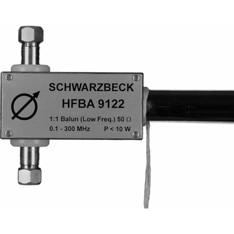
 Schwarzbeck HFBA 9122 HF-VHF Broadband Balun
New
- HF-VHF Broadband balun / holder
- (0.1) 0.15 - 300 (500) MHz
- Especially to measure very high field strength
- For use with BBAL 9136, BBA 9106, BBAK 9137, BBVK 9138
- BBVU 9135 or BBUK 9139 biconical elements required
PDF Downloads
Test Equipment Description
The 1:1 Balun/Holder HFBA 9122 was originally designed as passive field probe to measure very high fieldstrength at low frequencies from 100 kHz up. Depending on the element type in use the HFBA 9122 can be used up to 500 MHz. The charcteristics of HFBA 9122 in the VHF range are comparable to common biconical antennas. The HFBA 9122 balun accepts several biconical element sizes, e.g. BBVU 9135 or BBUK 9139, which allows an antenna factor shift to the desired application. In general the antenna factor rises (reduction of sensitivity) with smaller elements.

Application:
The HFBA 9122 can be assumed as an electrical short antenna (Hertzian Dipole with LE << l). The Antenna Factor decreases by 20 dB / decade of frequency below 100 MHz. The result is a 20 dB / decade of frequency decreasing fieldstrength measuring range as indicated in the diagram (a constant noise floor or a constant voltage reading was assumed). For measurements of high fieldstrength the following difficulties may arise: A measurement error might be induced by insufficient shielding effectiveness of coaxial cables and measuring receiver. The HFBA 9122 offers with by far more than 120 dB shielding effectiveness a value which is at least one order higher than the respective value of cables or receivers. Braid currents may affect the measurement results, therefore the used cables should be as short as possible. The presence of interfering braid currents can be checked by rotating the polarisation for 180 °. In cases where critical braid currents exist, the measured fieldstrength differs by far more than 1 dB.
A further method to determine the validity of the measured results is to remove the biconical elements and watch the reading (do not touch the element fixtures). If there is a considerable reading without elements, the reason might be either insufficient shielding effectiveness or braid currents. Braid currents can be supressed by using ferrite loaded cables. Typical commercially available ferrite loaded cables are nearly useless in the frequency range of interest (< 30 MHz) because of their insufficient outer conductor inductance. A workaround can be achieved by the following technique: A thin double braid coaxial cable is wound 4 to 6 times through a ferrite core of very high permeability. The spacing between the ferrite cores on the cable should be 0.5 m each.
In order to improve impedance matching the use of a fixed attenuator (e.g. 6 dB) is recommended since the short antenna elements have only capacitive characteristics and do not provide impedance matching therefore.
Calibration:
The Calibration of the HFBA 9122 was performed using two different methods: In the frequency range from 0.1 to approx. 20 MHz (depending on the element size) the electric field for calibration of the antenna factor is provided with a capacitor. Above 20 MHz the antenna calibration is made under quasi free space conditions using the 3 antenna method. The measurement uncertainty is +/- 1 dB for both methods (k=2).
| Specifications | |
| Frequency Range, nominal | 0.15 - 300 MHz |
| Frequency Range, usable | 0.1 - 500 MHz |
| Antenna Factor | ca. 95-15 dB/m |
| (depending on elem. type in use and frequency range) | |
| Fieldstrength Measuring Range | ca. 30-190 dBµV/m ca. 30µV/m - 3 kV/m |
| (depending on elem. type in use and frequency range) Länge Halterung | LH=555 mm Length holder: LH=555 mm |
| Width depends on elements used (see table accessories below) | |
| Antenna shaft (Tube) | Æ 22 mm |
| Total weight | 1.3 kg |
| Power (EMC TX) | 10 W |
| Coaxial Connector | N-Buchse / N - female |


