No products
Product successfully added to your shopping cart
There are 0 items in your cart. There is 1 item in your cart.
Schwarzbeck Dipole Antennas
- EMC Test Equipment
- Transient Generators
- RF Power Amplifiers
- DC - 300 kHz RF Amplifiers
- 10 kHz - 250 MHz RF Amplifiers
- 10 kHz - 400 MHz RF Amplifiers
- 10 kHz - 1 GHz RF Amplifiers
- 80 MHz - 1 GHz RF Amplifiers
- 1 GHz - 2 GHz RF Amplifiers
- 700 MHz - 4.2 GHz RF Amplifiers
- 1 GHz - 6 GHz RF Amplifiers
- 2 GHz - 8 GHz RF Amplifiers
- 6 GHz - 18 GHz RF Amplifiers
- 18 GHz - 40 GHz RF Amplifiers
- Pulse Amplifiers
- RF Field Strength Probes & Meters
- RF Conducted Immunity
- EMC Receivers/EMI Analyzers
- EMC Antennas
- Coupling Decoupling Networks (CDN's)
- Line Impedance Stabilization Networks (LISN's)
- RF Test Equipment
- EMC Probes
- EMC Measurement & Equipment Software
- Power Supplies
- Electrical Safety Analyzers
- High Precision Laboratory Power Analyzers & Meters
- Anechoic Chambers
- Over-the-Air (OTA) Test Chambers
- EMI RF Shielded Tent Enclosures
- RF Shielded Rooms
- EMC Absorber
- Positioning Equipment
- EMC/EMI Test Setup
- GTEM Cells / TEM Cells
- Reverberation Chambers
- Used RF Anechoic Chambers
- EMC Chamber Filters
- EMC Chamber Shielding Gaskets
- RF Shielded Doors
- Anechoic Chamber Accessories
- Fully Anechoic (FAR) Test Chambers
- Manufacturers
- 3ctest
- AE Techron
- AH Systems
- Amplifier Research
- Boonton
- Com-Power
- Diamond Engineering
- EM Test (Ametek CTS)
- EMC Partner
- EMC Test Design
- Empower High Power RF Amplifiers
- ETS-lindgren
- Log Periodic Dipole Array Antenna
- Near Field Probe Sets
- Double Ridge Horn Antennas
- Biconical Antennas
- Quad Ridge Horn Antennas
- Electric Field Probes
- GTEM's
- Positioners & Tripods
- Loop Antennas
- Biconilog Antennas
- LISN's (Line Impedance Stabilization Network)
- Shielded Enclosures/Rooms
- Monopole Antennas
- Field Generating Antennas
- Fischer Custom Communications
- Haefely Hipotronics
- Haefely EFT/Burst Immunity Test Systems
- Haefely Surge Combination Wave Test Systems
- Haefely Surge Damped Oscillating Wave Test Systems
- Haefely Electrostatic Discharge Test Systems (ESD)
- Haefely Surge Ring Wave Test Systems
- Haefely Surge Telecom Wave Test Systems
- Haefely Magnetic Field Test Systems
- Haefely CDN's (Coupling/Decoupling Networks)
- IFI Amplifiers
- Keysight (Agilent)
- MVG - Microwave Vision Group
- PMM / Narda
- Rohde & Schwarz RF Test Equipment
- Rohde & Schwarz Broadband RF Amplifiers
- Rohde & Schwarz Spectrum Analyzers
- Rohde & Schwarz Compliant EMI Test Receivers
- Rohde & Schwarz Isotropic RF Probes
- Rohde & Schwarz RF Signal Generators
- Rohde & Schwarz RF Switches
- Rohde & Schwarz Oscilloscopes
- Rohde & Schwarz RF Power Meters
- Rohde & Schwarz RF Power Sensors
- Schloder
- Schwarzbeck Mess-Elektronik
- Schwarzbeck Antennas
- Schwarzbeck Automotive Antennas
- Schwarzbeck Broadband Horn Antennas
- Schwarzbeck Biconical Antennas
- Schwarzbeck Logarithmic Periodic Broadband Antennas
- Schwarzbeck Stacked Log-Periodic Broadband Antennas
- Schwarzbeck Biconic Log-Periodic Antennas
- Schwarzbeck Dipole Antennas
- Schwarzbeck Rod Antennas
- Schwarbeck Antenna Baluns / Holders
- Schwarzbeck LISN Line Impedance Stabilisation Networks
- Schwarbeck Decoupling & Absorbing Clamps
- Schwarzbeck Field Probes
- Schwarzbeck Helmholtz Coils
- Schwarzbeck Antenna Masts
- Schwarzbeck Coupling/Decoupling Networks
- Schwarzbeck Antennas
- Solar Electronics
- Teseq (Schaffner)
- Teseq Automotive Transient Generators
- Teseq RF Test Equipment
- Teseq EFT/Burst Generators
- Teseq RF Immunity Generators
- Teseq ESD Guns
- Teseq Surge Generators
- Teseq Harmonics & Flicker Solutions
- Teseq Dips, Interrupts & Variations Equipment
- Teseq Ring Wave Generators
- Teseq Oscillatory Waves Generators
- Teseq Absorbing Clamps / Ferrite Tube
- Teseq EMC Antennas
- Teseq Current Probes
- Teseq Coupling Networks
- Thermo Keytek
- Vicreate
- Compliance Standards
- International (IEC/EN)
- EN/IEC 61000-3-2
- EN/IEC 61000-3-3
- IEC 61000-3-11
- IEC / EN 610000-3-12
- EN/IEC 61000-4-2
- EN/IEC 61000-4-3
- EN/IEC 61000-4-4
- EN/IEC 61000-4-5
- EN/IEC 61000-4-6
- EN/IEC 61000-4-7
- EN/IEC 61000-4-8
- EN/IEC 61000-4-9
- EN/IEC 61000-4-10
- EN/IEC 61000-4-11
- EN/IEC 61000-4-12
- EN/IEC 61000-4-16
- EN/IEC 61000-4-18
- EN/IEC 61000-4-19
- EN/IEC 61000-4-20
- EN/IEC 61000-4-21
- EN/IEC 61000-4-29
- EN/IEC 61000-4-31
- IEC 61000-4-39
- EN/IEC 62132
- SEMI F47 Voltage Sag Immunity
- Product Standards
- Military & Aerospace Standards
- Automotive EMC Standards
- CISPR Standards
- Telecom Testing
- ANSI/IEEE Standards
- FCC Part 15
- FCC Part 30
- International (IEC/EN)
- Application/Test Type
- Radiated Immunity
- Bulk Current Injection Testing
- RF Emissions Testing
- Conducted Immunity
- Conducted Emissions
- Antenna Pattern Measurement
- CE Mark Testing
- Intentional Radiator Testing
- Pulsed HIRF Radar
- Over-the-Air (OTA) Testing
- 5G Test Solutions
- Automotive EMC
- SAR Measurement Equipment
- Radiated Emissions
- Battery Simulator Test Equipment
- Services
- Clearance
Viewed products
-

Schwarzbeck UHA 9125 D...
Tuneable UHF - Half - Wave Dipole...
 View larger
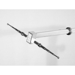
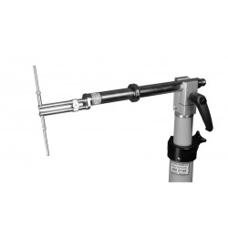
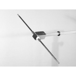
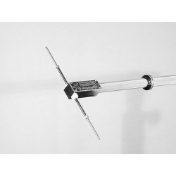
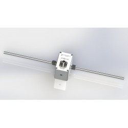
Schwarzbeck UHA 9125 D Half-Wave Dipole with EMI-Balun
New
- Tuneable UHF - Half - Wave Dipole
- With EMI - Balun
- 1.0 - 3 (4) GHz with 6 sets of elements
- LE = 140, 114, 90, 72, 60, 48 mm
PDF Downloads
Test Equipment Description
The low loss half wave dipole Schwarzbeck UHA 9125 D has a usable frequency range from 1 GHz to 4 GHz. Depending on the desired center frequency, dipole elements with the corresponding length are supplied. The moveable shorting bar is set to a quarter wavelength to provide a good symmetry.

| Schwarzbeck UHA 9125 D Specifications | |
| Frequency Range | 1 - 3 (4) GHz |
| Impedance | 50 Ω |
| Isotropic Gain | 2.15 dBi (theoret.) |
| Gain over Half Wave Dipole | 0 dBd (theoret.) |
| Maximum Input Power | 100 W |
| Directive Patterns | |
| 3 dB Half Power Beamwidth (E-Plane) | 78° |
| H-Plane | circular |
Schwarzbeck UHA 9125 D Application:
Half wave dipoles are often used to generate defined radiated power. The dipole is fed with RF-power, leading to the same fieldstrength reading, as created by the EuT before. (EuT is substituted by a dipole) The required RF-power at the dipole's N-connector is determined, representing the ERP-value (Effective Radiated Power). To obtain the EIRP-value (Effective Isotropic Radiated Power), the RF-power has to be increased by 2.15 dB, because an ideal half wave dipole has an isotropic gain of 2.15 dBi.
Schwarzbeck UHA 9125 D Directional Patterns:


Due to unwanted, but unavoidable reflections at mast adapter, indexing ring and cable etc. the shown directional patterns deviate somewhat from the theoretical pattern shape (typically less than 1 dB). The H-plane pattern of an ideal halfwave dipole is circular. The half power beamwidth (- 3 dB) of the ideal half-wave dipole is 78°. The reflections in the antennas' direct surrounding increase the gain figure in forward direction (to the right in the above sketch) by +0.5 dB typically (theoretical isotropic gain of a half-wave dipole: 2.15 dBi).
Schwarzbeck UHA 9125 D Hints:
The extremely low loss half wave dipole UHA 9125 D can be used without correction factors for nearly all applications. The losses are negligible small (typ. < 0.1 dB). The directive pattern of an ideal half wave dipole is circular in the H-plane, the E-plane offers a pattern similar to an "8".
The maxima can be found perpendicular to the dipole elements. The minima of the E-plane pattern are found on the dipole element axis. The theoretical isotropic gain figure of a half wave dipole is 2.15 dBi, this value might be exceeded slightly (up to + 0.5 dB) in calibration data.
The reason for this gain increase are unwanted reflexions at the mast adapter and other mounting equipment. Since even non metallic materials are very reflective in the microwave frequency range, the mast adapter should be as small as possible in order to minimize the influence on the circular radiation pattern. Suitable mast adapters have an influence of less than 1 dB on the H-plane directivity. If the dipole is set up for vertical polarisation, the coaxial cable should be continued in the same direction as the 22 mm tube as long as possible, otherwise unwanted reflections may affect the measurement results.
The setting of the moveable shorting bar is not critical, even a tolerance margin of +/- 2 mm has a negligible influence on the gain figure. The high operating frequencies require a very small antenna size and a filigree making. Therefore the Antenna should be handled with great care. Bent or damaged element holder threads are not a part of manufacturers' warranty.

| Element Length | Moveable Short Position | Half-wave resonance | Frequency of maximum gain | Frequency of best impedance matching | Bandwidth with 0.5 dB gain decay | Bandwidth with 1 dB gain decay |
| L E | L S | fλ/2 | f gimax | fSWRmin | B[-0.5 dB] | B[-1 dB] |
| [mm] | [mm] | [GHz] | [GHz] | [GHz] | [GHz] | [GHz] |
| 140 | removed | 1.07 | 0.98 | 0.96 | 0.92 - 1.03 | 0.9 - 1.07 |
| 114 | removed | 1.32 | 1.2 | 1.19 | 1.1-1.35 | 1.07-1.65 |
| 90 | 45 | 1.67 | 1.65 | 1.52 | 1.4 - 1.8 | 1.4 - 2.15 |
| 72 | 36 | 2.08 | 2.0 | 1.9 | 1.7 - 2.3 | 1.65 - 2.45 |
| 60 | 30 | 2.50 | 2.3 | 2.3 | 2.1 - 2.7 | 2.03 - 2.75 |
| 48 | 24 | 3.13 | 3.3 | 3.1 | 2.8 - 3.7 | 2.65 - 3.8 |
| Other Element Lengths are available on request | ||||||
Since unwanted reflections are apparent in all practical applications, the tabular values have been determined using a multiple averaging technique (different distances, different angles of the H-plane pattern, height variation). To obtain best measurement results the mast / adapter should be as small as possible.