

Send Enquiry For AH Systems SAS-575 Double Ridge Guide Horn Antenna, 1 GHz to 4 GHz, 250 Watts, 200 V/M
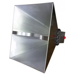
AH Systems SAS-575 Double Ridge Guide Horn Antenna, 1 GHz to 4 GHz, 250 Watts, 200 V/M
- Broad Frequency Range of 1 GHz to 4 GHz
- Linearly Polarized High Gain, Low VSWR
- Individually Calibrated
- Three year Warranty


