No products
Product successfully added to your shopping cart
There are 0 items in your cart. There is 1 item in your cart.
Boonton RF Power Meters
- EMC Test Equipment
- Transient Generators
- RF Power Amplifiers
- DC - 300 kHz RF Amplifiers
- 10 kHz - 250 MHz RF Amplifiers
- 10 kHz - 400 MHz RF Amplifiers
- 10 kHz - 1 GHz RF Amplifiers
- 80 MHz - 1 GHz RF Amplifiers
- 1 GHz - 2 GHz RF Amplifiers
- 700 MHz - 4.2 GHz RF Amplifiers
- 1 GHz - 6 GHz RF Amplifiers
- 2 GHz - 8 GHz RF Amplifiers
- 6 GHz - 18 GHz RF Amplifiers
- 18 GHz - 40 GHz RF Amplifiers
- Pulse Amplifiers
- RF Field Strength Probes & Meters
- RF Conducted Immunity
- EMC Receivers/EMI Analyzers
- EMC Antennas
- Coupling Decoupling Networks (CDN's)
- Line Impedance Stabilization Networks (LISN's)
- RF Test Equipment
- EMC Probes
- EMC Measurement & Equipment Software
- Power Supplies
- Electrical Safety Analyzers
- High Precision Laboratory Power Analyzers & Meters
- Anechoic Chambers
- Over-the-Air (OTA) Test Chambers
- EMI RF Shielded Tent Enclosures
- RF Shielded Rooms
- EMC Absorber
- Positioning Equipment
- EMC/EMI Test Setup
- GTEM Cells / TEM Cells
- Reverberation Chambers
- Used RF Anechoic Chambers
- EMC Chamber Filters
- EMC Chamber Shielding Gaskets
- RF Shielded Doors
- Anechoic Chamber Accessories
- Fully Anechoic (FAR) Test Chambers
- Manufacturers
- 3ctest
- AE Techron
- AH Systems
- Amplifier Research
- Boonton
- Com-Power
- Diamond Engineering
- EM Test (Ametek CTS)
- EMC Partner
- EMC Test Design
- Empower High Power RF Amplifiers
- ETS-lindgren
- Log Periodic Dipole Array Antenna
- Near Field Probe Sets
- Double Ridge Horn Antennas
- Biconical Antennas
- Quad Ridge Horn Antennas
- Electric Field Probes
- GTEM's
- Positioners & Tripods
- Loop Antennas
- Biconilog Antennas
- LISN's (Line Impedance Stabilization Network)
- Shielded Enclosures/Rooms
- Monopole Antennas
- Field Generating Antennas
- Fischer Custom Communications
- Haefely Hipotronics
- Haefely EFT/Burst Immunity Test Systems
- Haefely Surge Combination Wave Test Systems
- Haefely Surge Damped Oscillating Wave Test Systems
- Haefely Electrostatic Discharge Test Systems (ESD)
- Haefely Surge Ring Wave Test Systems
- Haefely Surge Telecom Wave Test Systems
- Haefely Magnetic Field Test Systems
- Haefely CDN's (Coupling/Decoupling Networks)
- IFI Amplifiers
- Keysight (Agilent)
- MVG - Microwave Vision Group
- PMM / Narda
- Rohde & Schwarz RF Test Equipment
- Rohde & Schwarz Broadband RF Amplifiers
- Rohde & Schwarz Spectrum Analyzers
- Rohde & Schwarz Compliant EMI Test Receivers
- Rohde & Schwarz Isotropic RF Probes
- Rohde & Schwarz RF Signal Generators
- Rohde & Schwarz RF Switches
- Rohde & Schwarz Oscilloscopes
- Rohde & Schwarz RF Power Meters
- Rohde & Schwarz RF Power Sensors
- Schloder
- Schwarzbeck Mess-Elektronik
- Schwarzbeck Antennas
- Schwarzbeck Automotive Antennas
- Schwarzbeck Broadband Horn Antennas
- Schwarzbeck Biconical Antennas
- Schwarzbeck Logarithmic Periodic Broadband Antennas
- Schwarzbeck Stacked Log-Periodic Broadband Antennas
- Schwarzbeck Biconic Log-Periodic Antennas
- Schwarzbeck Dipole Antennas
- Schwarzbeck Rod Antennas
- Schwarbeck Antenna Baluns / Holders
- Schwarzbeck LISN Line Impedance Stabilisation Networks
- Schwarbeck Decoupling & Absorbing Clamps
- Schwarzbeck Field Probes
- Schwarzbeck Helmholtz Coils
- Schwarzbeck Antenna Masts
- Schwarzbeck Coupling/Decoupling Networks
- Schwarzbeck Antennas
- Solar Electronics
- Teseq (Schaffner)
- Teseq Automotive Transient Generators
- Teseq RF Test Equipment
- Teseq EFT/Burst Generators
- Teseq RF Immunity Generators
- Teseq ESD Guns
- Teseq Surge Generators
- Teseq Harmonics & Flicker Solutions
- Teseq Dips, Interrupts & Variations Equipment
- Teseq Ring Wave Generators
- Teseq Oscillatory Waves Generators
- Teseq Absorbing Clamps / Ferrite Tube
- Teseq EMC Antennas
- Teseq Current Probes
- Teseq Coupling Networks
- Thermo Keytek
- Vicreate
- Compliance Standards
- International (IEC/EN)
- EN/IEC 61000-3-2
- EN/IEC 61000-3-3
- IEC 61000-3-11
- IEC / EN 610000-3-12
- EN/IEC 61000-4-2
- EN/IEC 61000-4-3
- EN/IEC 61000-4-4
- EN/IEC 61000-4-5
- EN/IEC 61000-4-6
- EN/IEC 61000-4-7
- EN/IEC 61000-4-8
- EN/IEC 61000-4-9
- EN/IEC 61000-4-10
- EN/IEC 61000-4-11
- EN/IEC 61000-4-12
- EN/IEC 61000-4-16
- EN/IEC 61000-4-18
- EN/IEC 61000-4-19
- EN/IEC 61000-4-20
- EN/IEC 61000-4-21
- EN/IEC 61000-4-29
- EN/IEC 61000-4-31
- IEC 61000-4-39
- EN/IEC 62132
- SEMI F47 Voltage Sag Immunity
- Product Standards
- Military & Aerospace Standards
- Automotive EMC Standards
- CISPR Standards
- Telecom Testing
- ANSI/IEEE Standards
- FCC Part 15
- FCC Part 30
- International (IEC/EN)
- Application/Test Type
- Radiated Immunity
- Bulk Current Injection Testing
- RF Emissions Testing
- Conducted Immunity
- Conducted Emissions
- Antenna Pattern Measurement
- CE Mark Testing
- Intentional Radiator Testing
- Pulsed HIRF Radar
- Over-the-Air (OTA) Testing
- 5G Test Solutions
- Automotive EMC
- SAR Measurement Equipment
- Radiated Emissions
- Battery Simulator Test Equipment
- Services
- Clearance
Viewed products
-

Boonton 4541 Single...
1-Channel 200 ps Time Resolution 7 ns...
-

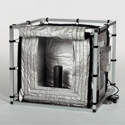
ETS-Lindgren (EMCO)...
DEI Concept Provides a Hear-through...


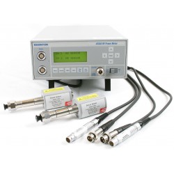
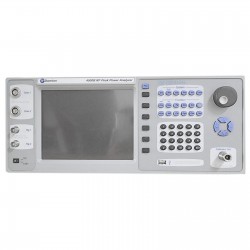
Boonton 4541 Single Channel Front Panel Input RF Power Meter
Used
- 1-Channel
- 200 ps Time Resolution
- 7 ns Rise Time
- Video Bandwidth up to 70 MHz
- 17 default presets plus storage for 25 user defined presets
- Fast statistical analysis including ccdf
- Bright, clear 4” color LCD display
PDF Downloads
Test Equipment Description
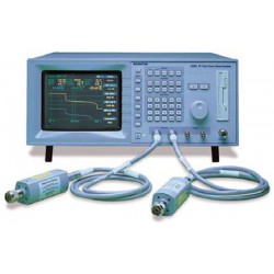
Boonton 4540 Series RF Power Meter
The Boonton 4540 Series RF Power Meter is the instrument of choice for capturing, displaying and analyzing RF signals. Applications include pulsed RF signals like radar or gsm based technologies, as well as pseudorandom, noise-like signals such as cdma, evdo, wlan, wimax, umts, hspa, lte, ofdm or hdtv. The 4540 Series offers Pulse, Modulated/CW, and Statistical operating modes, making it well suited for all requirements of R&D, manufacturing and control operations. Single channel versions (4541) and dual channel versions (4542) are available.
|
Both 4541 and 4542 |

Modulated, Pulsed and Statistical Measurements
Modulated Mode
Modulated Modemeasurements are possible with cost effective CW sensors, or with fast Peak Power sensors. Using Peak Power sensors, the 4540 Series can measure true average power of modulated waveforms, while providing important information about the instantaneous peak power value. Large digits allow clear, legible measurement reading.
Pulsed Mode
Analysis of fast single pulses or pulses with high pulse repetition interval (pri) requires an instrument with sophisticated trigger and data acquisition capability. This provides accuracy and high definition trace detail of the measured signal. A variety of trigger settings, including pre and post trigger in combination with a high sampling rate allow the 4540 Series to capture any pulse. High level of signal detail is essential when short pulses, signal edges, signal overshoots, filters, high gain amplifiers, delay lines and such have to be analyzed.
Statistical Mode
Non-periodic signals, such as hdtv, evdo, umts or lte are noise-like and consist of varying magnitude peaks randomly distributed over the channel. These random events do not serve as a trigger for consistent measurements. Amplifier designs require fast peak measurement capability from a power meter to detect signal clipping and compression due to overload. The Complementary Cumulative Distribution Function, or CCDF, displayed by the 4540 plots the probability that the power will be at or below a specified level. By examining the areas close to 100% probability, it is possible to see how often the highest peaks occur. It is easy to see amplifier compression under actual operating conditions, and to predict the effect on error rate that this may have. Up to 4 GSamples of data can be collected, compiled and analyzed by the 4540 Series.
 |  |  |
Clear and legible numeric display | The falling signal edge shows | Noise-like signals are analyzed statistically. |
Effective Random Sampling
The 4540 Series RF Power Meter offers an impressingly detailed representation of measured signals. As a result, signals can be analyzed thoroughly and anomalies can be detected imme- diately. High signal definition is achieved with two powerful features: a time resolution of 200ps, unprecedented in a power meter of this class, and a technique called Repetitive Random Sampling. For repetitive signals, the 4540 Series offers an effec- tive sampling rate of up to 5 gSamples / second.
Autoset/Preset
For accurate, repeatable measurements, power meters require diligently chosen trigger and timing settings. Finding the correct trigger settings is often more difficult than perform- ing the actual measurement – not so with the 4540 Series. Our instruments are equipped with an “AutoSet” feature. This feature analyzes incoming signals and presets the instrument’s timing and trigger settings in a way that allows for immediate measurements. Presets are available for many common wireless formats.
RF-Voltage Measurements
in some cases it is necessary to measure RF voltage without terminating or significantly loading the source. The 4540 Series supports voltage measurements with different Boonton voltage probes (also known as voltage sensors). Boonton’s high imped- ance voltage probes are available for frequencies from 10 hz to 1.2 ghz. voltage probes are designed to measure cw voltage to 10 v, but they can also be used to measure the root mean square (RMS) value of a fluctuating or modulated signal up to 20 mv (2 v with 1:100 divider). linearity correction factors are stored in the sensor adapter, so voltage measurements can be taken immediately.
Firmware Updates
Boonton strives to provide the best products to our customers, hence the 4540 Series can be easily field-updated with new firmware. New firmware versions are released periodically and available at the Boonton website. The download package comes with a loader that handles the proper update of the 4540 Series via a PC. Advantages of firmware updates are obvious: features added – for free.
|
The graphic header feature of the |

Virtual Front Panel Software
The 4540 virtual Front Panel software (vFP) can be down- loaded from the Boonton web site. it provides three powerful features:
- 4540 Series Remote Key Simulation
- Screenshots
- Full Screen Display
Remote Key Simulation allows simulating all the keys of the 4540 Series that is connected to the Pc via lAn. if more than one 4540 Series is present at the subnet, vFP software will detect all instruments and show their iP addresses and serial numbers. The operator can now select which instrument he wants to control. vFP does not switch the power meters into remote state; while controlled by vFP they still allow operation via the actual front panel keys.
Screenshots of traces are often required as records or when signals need to be analyzed at a later point in time. The 4540 vFP software takes a screenshot with one push of a button and stores the images as bitmap files.
The 4540 Series has a 4” display providing high resolution and great detail of the signal trace. Menu buttons can be hidden to increase the usable screen area. if an even larger screen display is required, the viewer function of the vFP transfers the 4540 Series screen live to a Pc to utilize the full screen size.
| 4540 Series Specifications | ||||||
| Acquisition and Measurement System | ||||||
| Measurement Technique Random repetitive sampling system providing pre and post-trigger data and statistical histogram accumulation | ||||||
| Sampling Rate | 50 MSa / second on each channel simultaneously | |||||
| Effective Sampling Rate | 5 GSa /second on each channel simultaneously | |||||
| Memory depth | 262,144 samples at max sampling rate | |||||
| Vertical Resolution | 0.008%, 14-bit A/D Converte | |||||
| DSP | 32 bit floating point | |||||
| Time resolution | 200 ps | |||||
| Sensor Inputs | ||||||
| RF Channels | 1 or 2 (4541 / 4542) | |||||
| RF Frequency Range | 10 kHz to 40 GHz* | |||||
| Pulse Meas. Range | -50 to +20 dBm* | |||||
| Modulated Meas. Range | -55 to +20 dBm* | |||||
| CW Pwr Range | -70 to +44 dBm* | |||||
| Relative Offset Range | ±200.00 dB | |||||
| Video BW | 70 MHz* | |||||
| Risetime | < 7 ns* | |||||
| Single Shot Bandwidth | 5 MHz (based on 10 samples/pulse) | |||||
| * Sensor Dependent, Calibrator Dependent | ||||||
| Vertical Scale | ||||||
| Logarithmic | ||||||
| 0.1 to 50 dBm/div | in 1-2-5 sequence | |||||
| 0.1 to 50 dBV/div | in 1-2-5 sequence | |||||
| 0.1 to 50 dBmV/div | in 1-2-5 sequence | |||||
| 0.1 to 50 dBuV/div | in 1-2-5 sequence | |||||
| Linear | ||||||
| 1 nW/div to 50 MW/div | in 1-2-5 sequence | |||||
| 1 nV/div to 50 MV/div | in 1-2-5 sequence | |||||
| Trigger | ||||||
| Mode | Normal, Auto, Auto Pk-to-Pk, Free Run | |||||
| Source | Channel 1 (internal) Channel 2 (internal) External | |||||
| Internal Level Range | -40 to +20 dBm (sensor dependent) | |||||
| External Level Range | ±5 volts (±50 volts with 10:1 divider probe) | |||||
| External Input Impedance | 1 MOhm (13 pF DC Coupled) | |||||
| Slope | + or – | |||||
| Hold-off | 0.0 - 1.0 sec (10 ns resolution) | |||||
| Min Trigger Pulse Width | 15 ns | |||||
| Max Trigger Rate | 30 MHz | |||||
| Time Base | ||||||
| Time Base Resolution | 200 ps | |||||
| Time Base Range | 10 ns/div to 1 hr/div | |||||
| Time Base Accuracy | 0.01% | |||||
| Time Base Display | Sweeping or Roll Mode | |||||
| Trigger Delay Range | ||||||
| Timebases 10 ns to 500 ns: | -4 ms to +100 ms | |||||
| Timebases 1 us to 10 ms: | ±4000 divisions | |||||
| Timebases 20 ms to 3600 s: | -40 s to +100 s | |||||
| Trigger Delay Resolution | 0.02 divisions | |||||
| Pulse Mode Operation | ||||||
| Automatic Measurements | ||||||
| Pulse width | Pulse rise-time | |||||
| Pulse fall-time | Pulse period | |||||
| Pulse repetition frequency | Pulse duty cycle | |||||
| Pulse off-time | Peak power | |||||
| Pulse “on” power | Pulse overshoot (dB or %) | |||||
| Waveform Average power | Top level power (IEEE spec) | |||||
| Bottom level power (IEEE spec) | Edge delay | |||||
| Edge skew (2 channel instruments only) | ||||||
| Marker Measurements | ||||||
| Markers (vertical cursors) | Settable in time relative to the trigger position | |||||
| Markers independently | Average, minimum, peak power at a single time offset | |||||
| Pair of Markers | Average, minimum, peak power over the interval between markers, power ratio between markers | |||||
| Acquisition Mode | Discontinuous triggered sample acquisition | |||||
| Trace Display | Power versus time swept trace (rolled trace for slow time bases) | |||||
| Trace Averaging | 1 to 16384 samples per sweep data point, exponential | |||||
| Modulated Mode Operation | ||||||
| Automatic Measurements | ||||||
| Average power | Peak power | Minimum power | ||||
| Peak to Average ratio | Dynamic range | |||||
| Signal Filtering | “Sliding window” filter; 0.002 to 16.0 seconds (fixed) or auto-filter | |||||
| Acquisition Mode | Continuous (un-triggered) sample acquisition | |||||
| Trace Display | Power versus time rolled trace | |||||
| Channel Math | Ratio, sum (power sensors) or difference (voltage sensors) between channels or between a channel and a reference measurement | |||||
| Statistical Mode Operation | ||||||
| Acquisition Mode | Continuous sample acquisition | |||||
| Sampling Rate | Configuration dependent | |||||
| Number of Histogram Bins | 16,384 | |||||
| Bin Power Resolution | <0.02 dB (statistical measurements) | |||||
| Limit Count | Adjustable, 2 – 4096 MSamples | |||||
| Terminal Action | Stop, flush and or decimate | |||||
| Graph Presentation | Normalized CCDF trace (relative to maximum power) | |||||
| Horizontal Scale | 0.1 to 5 dB/div | |||||
| Horizontal Offset | ±50.00 dBr | |||||
| Vertical Axis | 0.0001 to 100% (Log, 6 decades) | |||||
| Text Measurements | ||||||
| Average, Peak and Minimum absolute power, Peak-to-Average and Dynamic Range ratios CCDF table (Peak/Average ratios at decade-spaced % CCDF intervals) | ||||||
| Cursor Measurements | ||||||
| Peak-to-Average ratio at specified % CCDF % CCDF at specified Peak-to-Average ratio | ||||||
| Status Display | Total acquisition time (MM:SS) Total acquired Samples | |||||
| Field Parameter | ||||||
| Measurements, settings, parameters & channel math that can be displayed (User selectable) | ||||||
| Chan Frequency | Vertical Scale | Vertical Center | dB Offset | |||
| Sensor Temp | Avg CW Power | Max Power | Min Power | |||
| Peak / Avg | Dynamic Range | Marker Avg | Marker Max | |||
| Marker Pk/Avg | Marker1 Level | Marker2 Level | Marker Delta | |||
| Marker Max Avg | Marker Min Avg | Marker1 Min | Marker1 Max | |||
| Marker2 Min | Marker2 Max | Marker Ratio | Mark Rev | |||
| Ratio | Mark Rev Delta | CH1-CH2 | CH2-CH1 | |||
| CH1+CH2 | CH1/CH2 | CH2/CH1 | Reference 1 | |||
| Reference 2 | CH1/Ref1 | CH1-Ref1 | CH2+Ref1 | |||
| CH2/Ref2 | CH2-Ref2 | CH2+Ref2 | vacant to | |||
| Calibration Source | ||||||
| Internal Calibrator | ||||||
| Operating Modes | Off, On CW | |||||
| Frequency | 50.025 MHz ± 0.1% | |||||
| Level Range | -60 to +20 dBm | |||||
| Resolution | 0.1 dB | |||||
| RF Connector | Type N | |||||
| Source VSWR | 1.05 (reflection coefficient = 0.024) | |||||
| Accuracy, 0C to 20C, NIST traceable | ||||||
| 0 dBm | ±0.055 dB (1.27%) | |||||
| +20 to -39 dBm | ±0.075 dB (1.74%) | |||||
| -40 to -60 dBm | ±0.105 dB (2.45%) | |||||
| Auto-calibration | Automatically generated linearity calibration data for peak power sensors | |||||
| Measurement Setup / Storage | ||||||
| 25 complete user defined settings (save & recall) | ||||||
| Presets | ||||||
| Default | GSM | EDGE | NADC | |||
| Bluetooth | cdmaOne | W-CDMA | CDMA2000 | |||
| iDEN | RADAR | MCPA | WiFi 802.11a | |||
| 802.11b/g | 1xEV-DO | 1xEV-DV | TD-SCDMA | |||
| DVB | HiperLAN2 | |||||
| External Interfaces | ||||||
| Remote Control | ||||||
| GPIB | Complies with IEEE-488.1 and SCPI version 1993. Implements AH1, SH1, T6, LE0, SR1, RL1, PP0, DC1, DT1, C0, and E1. | |||||
| LAN | TCP/IP Ethernet Programmable interfaces | |||||
| USB | “USB Device”, Type-B connector | |||||
| Multi I/O BNC connector | ||||||
| User selectable | Status, trigger, alarm or voltage output | |||||
| Range | 0 to 10 V (Analog unipolar) -10 V to +10 V (Analog bipolar) 0 or 5 V (Logic) | |||||
| Accuracy | ±200 mV (±100 mV typical) | |||||
| Linearity | 0.1% typical | |||||
| VGA Out / Ext Cal | ||||||
| HDB-15 connector, video output (320x240) for VGA compatible analog RGB video monitor or external calibrator control interface for Model 2530 calibrator | ||||||
| Physical And Environmental Characteristics | ||||||
| Case Dimensions | 8.4 W x 3.5 H x 13.5 D inches (21.3 x 8.9 x 34.3 cm), Half-rack width, 2U height | |||||
| Weight | 90 to 260 VAC, 47 to 60 Hz 90 to 135 VAC, 47 to 400 Hz 50 W (70 VA) | |||||
| Power Requirements | 90 to 260 VAC, 47 to 60 Hz 90 to 135 VAC, 47 to 400 Hz 50 W (70 VA) | |||||
| Operating Temperature | 0 to 50 deg C (32 F to 122 F) | |||||
| Storage Temperature | -40 to +75 deg C (-40 F to 167 F) | |||||
| Ventilation | Thermostatically controlled fan | |||||
| Humidity | 95% maximum, non-condensing | |||||
| Altitude | Operation up to 15,000 feet (4575 m) | |||||
| Shock | Withstands ±5 G, 11 ms impulse in X, Y, and Z axes, as per EN 60068-2-27 | |||||
| Vibration | Withstands 2 G sine, 1.25 G random, as per EN 60068-2-6 and EN 60068-2-64 | |||||
| Other Characteristics | ||||||
| Display | 4.0” Diagonal TFT color LCD, 320 x 240 pixels, CCFL backlight | |||||
| Keyboard | 27 Key conductive rubber | |||||
| Main Computer | 32-bit Floating Point embedded processor | |||||
| DSP | 32-bit Floating Point DSP | |||||
| Battery | User-replaceable BR2325 lithium coin cell (alkaline cells optional), typical life: >10 years (lithium) | |||||
| Regulatory Categories | ||||||
| Full CE compliance with the following European Union directives and standards | ||||||
| Low Voltage Directive 2006/95/EC EN 60950-1:2002 for safety | ||||||
| Electromagnetic Compatibility Directive (EMC) 2004/108/EC EN 61326:1997 + A1:1998 + A2:2001 + A3:2003 | ||||||
| RoHS Directive 2002/95/EC for material safety | ||||||
| Manufactured to the intent of MIL-T28800E, Type III, Class 5, Style E | ||||||
| Sensors / Voltage Probes | ||||||
| Peak Power | ||||||
| Model | Frequency Range | Dynamic Range | Rise Time (Bandwidth) | |||
| 57006 | 0.05 to 6.0 GHz | -50 to +20 dBm | <7 ns (70 MHz) | |||
| 59318 | 0.05 to 18.0 GHz | -24 to +20 dBm | <10 ns (50 MHz) | |||
| 57518 | 0.05 to 18.0 GHz | -40 to +20 dBm | <100 ns (6 MHz) | |||
| 59340 | 0.05 to 40.0 GHz | -24 to +20 dBm | <10 ns (50 MHz) | |||
| 57540 | 0.05 to 40.0 GHz | -40 to +20 dBm | <100 ns (6 MHz) | |||
| CW Power | ||||||
| Wide Dynamic Range | ||||||
| Model | Frequency Range | Dynamic Range | ||||
| 51071A | 10 MHz to 26.5 GHz | -70 to +20 dBm | ||||
| 51072A | 30 MHz to 40 GHz | -70 to +20 dBm | ||||
| 51075A | 500 kHz to 18 GHz | -70 to +20 dBm | ||||
| 51077A | 500 kHz to 18 GHz | -60 to +30 dBm | ||||
| 51079A | 500 kHz to 18 GHz | -50 to +40 dBm | ||||
| Thermocouple | ||||||
| Model | Frequency Range | Dynamic Range | ||||
| 551100 (9E) | 10 MHz to 18 GHz | -20 to +20 dBm | ||||
| 51200 | 10 MHz to 18 GHz z | 0 to +37 dBm | ||||
| Special Purpose | ||||||
| Model | Frequency Range | Dynamic Range | ||||
| 51011 (EMC) | 10 kHz to 8GHz | -60 to +20 dBm (DC coupled) | ||||
| 51011 (4B) | 100 kHz to 12.4 GHz | -60 to +20 dBm | ||||
| 51013 (4E) | 100 kHz to 18 GHz | -60 to +20 dBm | ||||
| 51015 (5E) | 100 kHz to 18 GHz | -50 to +30 dBm | ||||
| 51033 (6E) | 100 kHz to 18 GHz | -40 to +33 dBm | ||||
| 51078 | 100 kHz to 18 GHz | -20 to +37 dBm | ||||
| Diode Average | ||||||
| Model | Frequency Range | Dynamic Range | ||||
| 51085 | 500 kHz to 18GHz | -30 to +20 dBm | ||||
| For 51085 Peak Power - 1kW peak, 5μs pulse width, 0.25% duty cycle For 51085 CW Power - 5W (+37dBm) average to 25°C ambient temperature, derated linearly to 2W (+33dBm) at 85°C | ||||||
| Voltage Probes | ||||||
| 95206302A | RF-Voltage Probe Kit 10 kHz - 1.2 GHz | |||||
| 95206402A | Low Frequency Voltage Probe Kit 10 Hz - 100 MHz | |||||
Go to top