
No products
Product successfully added to your shopping cart
There are 0 items in your cart. There is 1 item in your cart.
EMC Probes
- EMC Test Equipment
- Transient Generators
- RF Power Amplifiers
- DC - 300 kHz RF Amplifiers
- 10 kHz - 250 MHz RF Amplifiers
- 10 kHz - 400 MHz RF Amplifiers
- 10 kHz - 1 GHz RF Amplifiers
- 80 MHz - 1 GHz RF Amplifiers
- 1 GHz - 2 GHz RF Amplifiers
- 700 MHz - 4.2 GHz RF Amplifiers
- 1 GHz - 6 GHz RF Amplifiers
- 2 GHz - 8 GHz RF Amplifiers
- 6 GHz - 18 GHz RF Amplifiers
- 18 GHz - 40 GHz RF Amplifiers
- Pulse Amplifiers
- RF Field Strength Probes & Meters
- RF Conducted Immunity
- EMC Receivers/EMI Analyzers
- EMC Antennas
- Coupling Decoupling Networks (CDN's)
- Line Impedance Stabilization Networks (LISN's)
- RF Test Equipment
- EMC Probes
- EMC Measurement & Equipment Software
- Power Supplies
- Electrical Safety Analyzers
- High Precision Laboratory Power Analyzers & Meters
- Anechoic Chambers
- Over-the-Air (OTA) Test Chambers
- EMI RF Shielded Tent Enclosures
- RF Shielded Rooms
- EMC Absorber
- Positioning Equipment
- EMC/EMI Test Setup
- GTEM Cells / TEM Cells
- Reverberation Chambers
- Used RF Anechoic Chambers
- EMC Chamber Filters
- EMC Chamber Shielding Gaskets
- RF Shielded Doors
- Anechoic Chamber Accessories
- Fully Anechoic (FAR) Test Chambers
- Manufacturers
- 3ctest
- AE Techron
- AH Systems
- Amplifier Research
- Boonton
- Com-Power
- Diamond Engineering
- EM Test (Ametek CTS)
- EMC Partner
- EMC Test Design
- Empower High Power RF Amplifiers
- ETS-lindgren
- Log Periodic Dipole Array Antenna
- Near Field Probe Sets
- Double Ridge Horn Antennas
- Biconical Antennas
- Quad Ridge Horn Antennas
- Electric Field Probes
- GTEM's
- Positioners & Tripods
- Loop Antennas
- Biconilog Antennas
- LISN's (Line Impedance Stabilization Network)
- Shielded Enclosures/Rooms
- Monopole Antennas
- Field Generating Antennas
- Fischer Custom Communications
- Haefely Hipotronics
- Haefely EFT/Burst Immunity Test Systems
- Haefely Surge Combination Wave Test Systems
- Haefely Surge Damped Oscillating Wave Test Systems
- Haefely Electrostatic Discharge Test Systems (ESD)
- Haefely Surge Ring Wave Test Systems
- Haefely Surge Telecom Wave Test Systems
- Haefely Magnetic Field Test Systems
- Haefely CDN's (Coupling/Decoupling Networks)
- IFI Amplifiers
- Keysight (Agilent)
- MVG - Microwave Vision Group
- PMM / Narda
- Rohde & Schwarz RF Test Equipment
- Rohde & Schwarz Broadband RF Amplifiers
- Rohde & Schwarz Spectrum Analyzers
- Rohde & Schwarz Compliant EMI Test Receivers
- Rohde & Schwarz Isotropic RF Probes
- Rohde & Schwarz RF Signal Generators
- Rohde & Schwarz RF Switches
- Rohde & Schwarz Oscilloscopes
- Rohde & Schwarz RF Power Meters
- Rohde & Schwarz RF Power Sensors
- Schloder
- Schwarzbeck Mess-Elektronik
- Schwarzbeck Antennas
- Schwarzbeck Automotive Antennas
- Schwarzbeck Broadband Horn Antennas
- Schwarzbeck Biconical Antennas
- Schwarzbeck Logarithmic Periodic Broadband Antennas
- Schwarzbeck Stacked Log-Periodic Broadband Antennas
- Schwarzbeck Biconic Log-Periodic Antennas
- Schwarzbeck Dipole Antennas
- Schwarzbeck Rod Antennas
- Schwarbeck Antenna Baluns / Holders
- Schwarzbeck LISN Line Impedance Stabilisation Networks
- Schwarbeck Decoupling & Absorbing Clamps
- Schwarzbeck Field Probes
- Schwarzbeck Helmholtz Coils
- Schwarzbeck Antenna Masts
- Schwarzbeck Coupling/Decoupling Networks
- Schwarzbeck Antennas
- Solar Electronics
- Teseq (Schaffner)
- Teseq Automotive Transient Generators
- Teseq RF Test Equipment
- Teseq EFT/Burst Generators
- Teseq RF Immunity Generators
- Teseq ESD Guns
- Teseq Surge Generators
- Teseq Harmonics & Flicker Solutions
- Teseq Dips, Interrupts & Variations Equipment
- Teseq Ring Wave Generators
- Teseq Oscillatory Waves Generators
- Teseq Absorbing Clamps / Ferrite Tube
- Teseq EMC Antennas
- Teseq Current Probes
- Teseq Coupling Networks
- Thermo Keytek
- Vicreate
- Compliance Standards
- International (IEC/EN)
- EN/IEC 61000-3-2
- EN/IEC 61000-3-3
- IEC 61000-3-11
- IEC / EN 610000-3-12
- EN/IEC 61000-4-2
- EN/IEC 61000-4-3
- EN/IEC 61000-4-4
- EN/IEC 61000-4-5
- EN/IEC 61000-4-6
- EN/IEC 61000-4-7
- EN/IEC 61000-4-8
- EN/IEC 61000-4-9
- EN/IEC 61000-4-10
- EN/IEC 61000-4-11
- EN/IEC 61000-4-12
- EN/IEC 61000-4-16
- EN/IEC 61000-4-18
- EN/IEC 61000-4-19
- EN/IEC 61000-4-20
- EN/IEC 61000-4-21
- EN/IEC 61000-4-29
- EN/IEC 61000-4-31
- IEC 61000-4-39
- EN/IEC 62132
- SEMI F47 Voltage Sag Immunity
- Product Standards
- Military & Aerospace Standards
- Automotive EMC Standards
- CISPR Standards
- Telecom Testing
- ANSI/IEEE Standards
- FCC Part 15
- FCC Part 30
- International (IEC/EN)
- Application/Test Type
- Radiated Immunity
- Bulk Current Injection Testing
- RF Emissions Testing
- Conducted Immunity
- Conducted Emissions
- Antenna Pattern Measurement
- CE Mark Testing
- Intentional Radiator Testing
- Pulsed HIRF Radar
- Over-the-Air (OTA) Testing
- 5G Test Solutions
- Automotive EMC
- SAR Measurement Equipment
- Radiated Emissions
- Battery Simulator Test Equipment
- Services
- Clearance
Viewed products
-

Schwarzbeck TK 9420...
9 kHz - 30 MHz High Voltage Probe 1.5...
-

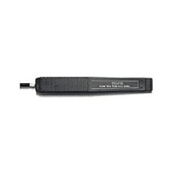
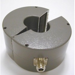
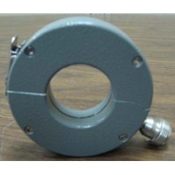
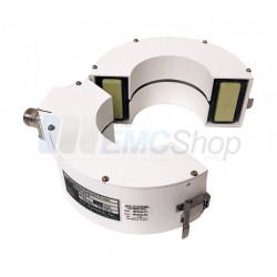
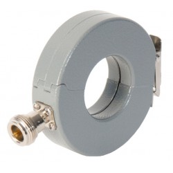
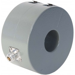
Schwarzbeck HFRA 5157...
0-20(30) MHz Frequency Range Circular...
 View larger
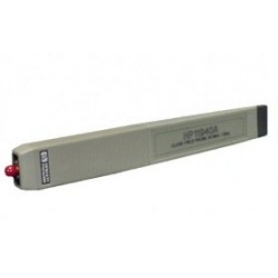
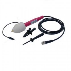
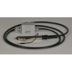
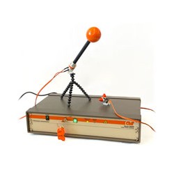
Schwarzbeck TK 9420 High Voltage Probe
New
- 9 kHz - 30 MHz
- High Voltage Probe
- 1.5 kOhm
- 4 pF
- RF < 30 V
In Stock
PDF Downloads
Test Equipment Description

APPLICATION
The voltage probe is preferred for applications in which the use of LISNs is difficult or even impossible due to high current consumption of the EuT. 30dB have to be added to the EMI receiver reading in dB over 1µV across 50 W to obtain the rf-voltage at the probe tip in the main frequency range 20 kHz to 30 MHz (across 1.5 kW //4pF). With lower frequencies (approx. 20 kHz down) use the diagram value above instead of 30 dB to correct for the voltage division of the coupling capacitor.
For function checks of the probe with sine wave signal generators be aware of the output voltage calibration reference with the usual 50 W load. Either connect a small carbon resistor of 50 W in parallel to the probe; otherwise almost 6 dB higher reading (twice the indic. generator voltage) will be observed. The probe is not shielded to keep the input load capacitance down to only 4 pF. In the presence of strong E fields it might be necessary to slide a metal tube or a copper foil over the probe body and connect it to ground.
The divider (option) can be used to determine the approximate RF-Impedance of unknown EuTs according to CISPR 16-2. Two measurements are required to estimate the Impedance, one without divider and one with the voltage probe and divider. The dBdifference of both readings is used to determine the EuT-Impedance out of the diagram. The method should be regarded as an estimation only. The uncertainty increases for frequencies above 10 MHz.
Example: The reading with voltage probe only was 60 dBµV. Using the divider a reading of 55 dBµV was achieved. The difference (indication change) is 5 dB. The corresponding Impedance value in the diagram is 400 W. In this case the measurement error is 2 dB.
WARNING
This probe must be used by qualified personnel only. Check if local warnings exist. The connection to the DuT terminals must be made before the high voltage is applied. After turn-on the body of the probe must not be touched (in spite of the insulating tube). The test receiver is usually grounded via the protection earth conductor, so the ground terminal of the probe is also at ground potential. At R. F. the ground connection must be short and near the "hot" terminal. The relevant safety standards for working with high voltage must be taken into account!
| Schwarzbeck TK 9420 Specifications | ||
| Input Impedance | 1.5 kΩ || 4 pF | |
| Frequency Range | 9 kHz - 30 MHz | |
| Voltage Range | HF: AC 50/60 Hz: < 2.5 kV DC: < 4.4 kV | |
| Freq. Range w. constant Correction of 30 dB | 20 kHz - 30 MHz | |
| Accuracy of Voltage Division | 30 kHz - 30 MHz +/- 0.5 dB | |
| Input Impedance of Test Receiver | 50 Ω, SWR ≤ 1.1 | |
| Internal Coupling Capacitor | 10 nF | |
| Terminals | 4 mm | |
| Ground Connection | insulated litz wire, Banana plug 4 mm | |
| Coax Cable | RG 58, 2 m, BNC | |
| Audio Frequency Impedance | 10 nF + 1.5 kΩ | |
| Weight | 180 g | |
| Dimensions | 175 mm x 23 mm ∅ | |
Associated EMC Test Equipment

30 other products in the same category:
-
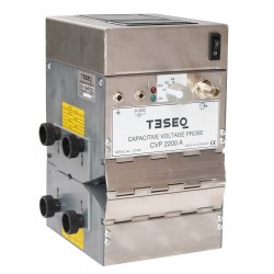
Teseq CVP 2200A Capacitive Voltage Probe
-
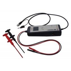
Teseq MD 210 High Voltage Differential Probe
-
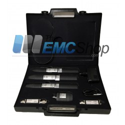
Rent Teseq NFPS-1 Near Field Probe Set
-
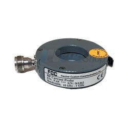
Fischer (FCC) F-65 RF Current Monitoring Probe, 10 kHz - 1 GHz
-

Pearson 411 Surge Current Monitor up to 5kA Peak Current, 1Hz to 20 MHz
-
Agilent (HP) 11940A Close Field Probe, 30 MHz to 1 GHz
-
Agilent (HP) 11941A Close Field Probe, 9 kHz - 30 MHz
-
Fischer Custom Communications FCC F-120-1 Bulk Current Injection Probe
-
Fischer Custom Communications F-61 Current Monitor Probe, 1 MHz - 1 GHz
-
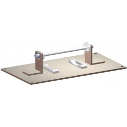
AH Systems CPF-631 Current Probe Calibration Fixture
-
AH Systems BCP-614 Probe to Measure Conducted RF Currents, 10 KHz - 300 MHz
-
Narda SHC-2/1000 CISPR Passive Voltage Probes
-
Keysight N9311X-100 Close Field Probe Set, 30 MHz to 3 GHz
-
Fischer F-120-6A Bulk Current Injection Probe, 10 kHz – 400 MHz, 100 Watts, less than 9 dB Insertion Loss
-
Fischer F-55 Current Emissions Probe, 10 kHz – 500 MHz, 350 Amps,
-
Schwarzbeck TK 9261 Active Voltage Probe 0.1 - 100 MHz
-
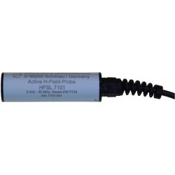
Schwarzbeck HFSL 7101 Active Magnetic Field Probe
-
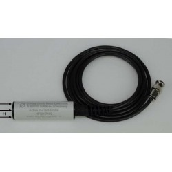
Schwarzbeck HFSH 7102 Active Magnetic Field Probe
-
Fischer F-130A-1 Bulk Current Injection Probe
-

Fischer F-140 Bulk Current Injection Probe
-
Fischer F-33-2 Current Monitor Probe
-
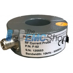
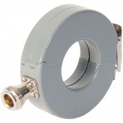
Fischer F-52 Current Monitor Probe
-

Fischer FCC-BCICF-1 Bulk Current Injection Probe Fixtures
-
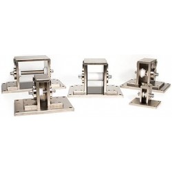
Fischer FCC-BCICF-2 Bulk Current Injection Probe Fixtures
-
Fischer FCC-BCICF-6-150 Bulk Current Injection Probe Fixtures
-
Narda EF 5092 50 GHz Electric field Probe for NBM Meter
-
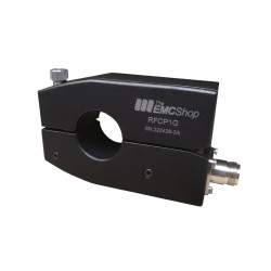
RFCP1G EMI Current Probe 10 kHz to 1GHz
-
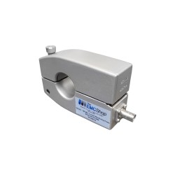
RFCP150M RF Current Montioring Probe 10k - 150M
-
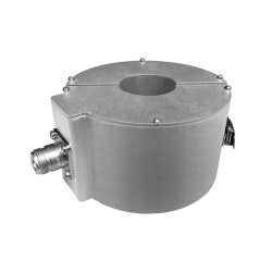
RFCP300M RFI Current Sensing Probe 20 Hz to 300 MHz
-
Amplifier Research FL8009 Laser-Powered Electric Field Probe Kit, 20 MHz – 9.3 GHz, CW & Pulse