
No products
Product successfully added to your shopping cart
There are 0 items in your cart. There is 1 item in your cart.
IEC 61000-4-6 CDNs for Unscreened Balanced Lines
- EMC Test Equipment
- Transient Generators
- RF Power Amplifiers
- DC - 300 kHz RF Amplifiers
- 10 kHz - 250 MHz RF Amplifiers
- 10 kHz - 400 MHz RF Amplifiers
- 10 kHz - 1 GHz RF Amplifiers
- 80 MHz - 1 GHz RF Amplifiers
- 1 GHz - 2 GHz RF Amplifiers
- 700 MHz - 4.2 GHz RF Amplifiers
- 1 GHz - 6 GHz RF Amplifiers
- 2 GHz - 8 GHz RF Amplifiers
- 6 GHz - 18 GHz RF Amplifiers
- 18 GHz - 40 GHz RF Amplifiers
- Pulse Amplifiers
- RF Field Strength Probes & Meters
- RF Conducted Immunity
- EMC Receivers/EMI Analyzers
- EMC Antennas
- Coupling Decoupling Networks (CDN's)
- Line Impedance Stabilization Networks (LISN's)
- RF Test Equipment
- EMC Probes
- EMC Measurement & Equipment Software
- Power Supplies
- Electrical Safety Analyzers
- High Precision Laboratory Power Analyzers & Meters
- Anechoic Chambers
- Over-the-Air (OTA) Test Chambers
- EMI RF Shielded Tent Enclosures
- RF Shielded Rooms
- EMC Absorber
- Positioning Equipment
- EMC/EMI Test Setup
- GTEM Cells / TEM Cells
- Reverberation Chambers
- Used RF Anechoic Chambers
- EMC Chamber Filters
- EMC Chamber Shielding Gaskets
- RF Shielded Doors
- Anechoic Chamber Accessories
- Fully Anechoic (FAR) Test Chambers
- Manufacturers
- 3ctest
- AE Techron
- AH Systems
- Amplifier Research
- Boonton
- Com-Power
- Diamond Engineering
- EM Test (Ametek CTS)
- EMC Partner
- EMC Test Design
- Empower High Power RF Amplifiers
- ETS-lindgren
- Log Periodic Dipole Array Antenna
- Near Field Probe Sets
- Double Ridge Horn Antennas
- Biconical Antennas
- Quad Ridge Horn Antennas
- Electric Field Probes
- GTEM's
- Positioners & Tripods
- Loop Antennas
- Biconilog Antennas
- LISN's (Line Impedance Stabilization Network)
- Shielded Enclosures/Rooms
- Monopole Antennas
- Field Generating Antennas
- Fischer Custom Communications
- Haefely Hipotronics
- Haefely EFT/Burst Immunity Test Systems
- Haefely Surge Combination Wave Test Systems
- Haefely Surge Damped Oscillating Wave Test Systems
- Haefely Electrostatic Discharge Test Systems (ESD)
- Haefely Surge Ring Wave Test Systems
- Haefely Surge Telecom Wave Test Systems
- Haefely Magnetic Field Test Systems
- Haefely CDN's (Coupling/Decoupling Networks)
- IFI Amplifiers
- Keysight (Agilent)
- MVG - Microwave Vision Group
- PMM / Narda
- Rohde & Schwarz RF Test Equipment
- Rohde & Schwarz Broadband RF Amplifiers
- Rohde & Schwarz Spectrum Analyzers
- Rohde & Schwarz Compliant EMI Test Receivers
- Rohde & Schwarz Isotropic RF Probes
- Rohde & Schwarz RF Signal Generators
- Rohde & Schwarz RF Switches
- Rohde & Schwarz Oscilloscopes
- Rohde & Schwarz RF Power Meters
- Rohde & Schwarz RF Power Sensors
- Schloder
- Schwarzbeck Mess-Elektronik
- Schwarzbeck Antennas
- Schwarzbeck Automotive Antennas
- Schwarzbeck Broadband Horn Antennas
- Schwarzbeck Biconical Antennas
- Schwarzbeck Logarithmic Periodic Broadband Antennas
- Schwarzbeck Stacked Log-Periodic Broadband Antennas
- Schwarzbeck Biconic Log-Periodic Antennas
- Schwarzbeck Dipole Antennas
- Schwarzbeck Rod Antennas
- Schwarbeck Antenna Baluns / Holders
- Schwarzbeck LISN Line Impedance Stabilisation Networks
- Schwarbeck Decoupling & Absorbing Clamps
- Schwarzbeck Field Probes
- Schwarzbeck Helmholtz Coils
- Schwarzbeck Antenna Masts
- Schwarzbeck Coupling/Decoupling Networks
- Schwarzbeck Antennas
- Solar Electronics
- Teseq (Schaffner)
- Teseq Automotive Transient Generators
- Teseq RF Test Equipment
- Teseq EFT/Burst Generators
- Teseq RF Immunity Generators
- Teseq ESD Guns
- Teseq Surge Generators
- Teseq Harmonics & Flicker Solutions
- Teseq Dips, Interrupts & Variations Equipment
- Teseq Ring Wave Generators
- Teseq Oscillatory Waves Generators
- Teseq Absorbing Clamps / Ferrite Tube
- Teseq EMC Antennas
- Teseq Current Probes
- Teseq Coupling Networks
- Thermo Keytek
- Vicreate
- Compliance Standards
- International (IEC/EN)
- EN/IEC 61000-3-2
- EN/IEC 61000-3-3
- IEC 61000-3-11
- IEC / EN 610000-3-12
- EN/IEC 61000-4-2
- EN/IEC 61000-4-3
- EN/IEC 61000-4-4
- EN/IEC 61000-4-5
- EN/IEC 61000-4-6
- EN/IEC 61000-4-7
- EN/IEC 61000-4-8
- EN/IEC 61000-4-9
- EN/IEC 61000-4-10
- EN/IEC 61000-4-11
- EN/IEC 61000-4-12
- EN/IEC 61000-4-16
- EN/IEC 61000-4-18
- EN/IEC 61000-4-19
- EN/IEC 61000-4-20
- EN/IEC 61000-4-21
- EN/IEC 61000-4-29
- EN/IEC 61000-4-31
- IEC 61000-4-39
- EN/IEC 62132
- SEMI F47 Voltage Sag Immunity
- Product Standards
- Military & Aerospace Standards
- Automotive EMC Standards
- CISPR Standards
- Telecom Testing
- ANSI/IEEE Standards
- FCC Part 15
- FCC Part 30
- International (IEC/EN)
- Application/Test Type
- Radiated Immunity
- Bulk Current Injection Testing
- RF Emissions Testing
- Conducted Immunity
- Conducted Emissions
- Antenna Pattern Measurement
- CE Mark Testing
- Intentional Radiator Testing
- Pulsed HIRF Radar
- Over-the-Air (OTA) Testing
- 5G Test Solutions
- Automotive EMC
- SAR Measurement Equipment
- Radiated Emissions
- Battery Simulator Test Equipment
- Services
- Clearance
Viewed products
-

Schwarzbeck NTFM 8158...
150 kHz – 30 MHz Frequency range...
 View larger
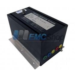
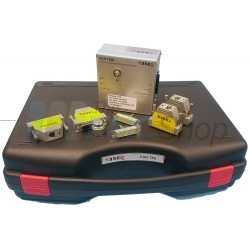
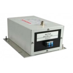
Schwarzbeck NTFM 8158 8-Wire Impedance Stabilization Network
New
- 150 kHz – 30 MHz Frequency range (ISN)
- 150 kHz – 80 MHz Frequency range (CDN)
- ISN T8 CAT6 (LCL = 75 dB) acc. CISPR 22 edition 5.2
- Figure D.3. for up to 4 pairs UTP.
PDF Downloads
Test Equipment Description
The Schwarzbeck NTFM 8158 allows to perform common mode disturbance voltage measurements on unshielded twisted pairs (UTP) or communication ports with 2, 4, 6 or 8 wires according to CISPR 22:2005 or EN 55022:2006. The Equipment under Test (EuT) or Auxiliary Equipment (AE) can be connected using the RJ-45 sockets. The pin assignment follows EIA/TIA-T568A/B. The electrical circuit of NTFM 8158 is designed according to CISPR 22 Edition 5.2, figure D.3. The ISN does not influence the transmission quality up to gigabit Ethernet.
The ISN-device NTFM 8158 provides an longitudinal conversion loss of typically 75 dB at the EuT port and allows to measure CAT6 devices. There are two further ISN available for measurements of CAT5 devices (CAT5 8158) and CAT3 devices (CAT3 8158) respectively.
In addition to the measurement of disturbance voltage the NTFM 8158 allows to perform measurements of conducted immunity acc. CISPR 24 or EN 55024 up to 80 MH. An additional 50 Ω to 150 Ω adapter (EAB8 50-150) acc. IEC 61000-4-6 is required. This adapter can easily be mounted to the NTFM 8158 and is available as an option.
The specification of NTFM 8158 is fully compliant to CISPR 22 Ed. 5.2 and verified according methods described in CISPR 16-1-2, Annex E.
Application
The telecommunication port of the device under test must be connected to the NTFM 8158 EuT-port. The NTFM 8158 provides the asymmetrical port termination of the EuT. Auxiliary Equipment (AE) which has to be operated together with the device under test must be connected to the AE-port of NTFM 8158.
The data communication is based on differential mode voltages on pairs of wires. If the virtual null in the electrical middle of the voltages shifts compared to reference ground the magnitude of this shift is called the asymmetrical disturbance voltage or the common mode voltage. This voltage is decoupled to the BNC-connector to be measured with a receiver. The nominal voltage division factor is 9.5 dB, i.e. the reading of the voltage at a 50 Ω receiver has to be increased by 9.5 dB. This results into the disturbance voltage.
The LCL describes the conversion of the wanted differential mode data signal along a transmission line into an unwanted common mode signal. The common mode signal could be radiated and might cause disturbance field strength.
The test set up is described in CISPR 22 more detailed. Special attention must be paid to low inductive grounding, i.e. grounding suitable for radio frequencies. This is achieved by placing the aluminium housing of the NTFM 8158 directly on the reference ground plane. The EuT cable and the AE cable must not be installed close or parallel to each other to avoid unwanted coupling between them.
Pin assignment
The Pin Assignment complies to EIA/TIAT568A/B. RJ-12 and RJ-14 connectors use pair 1 and pair 3, RJ-11 connectors use pair 1 of the RJ-45 jack which are located in the middle of the RJ-45 connector. Pins 1 and 6 of the RJ-12 are not useable then. Please note that using RJ-12, RJ-11 or RJ-14 connectors in RJ45 jacks leads to decreased lifespan of the RJ-45 jack.
If less than four pairs are measured, the unused wires are left unconnected.
| Paar/pair | PRJ-45 connector | RJ-12/RJ-14 connector | RJ-11 connector |
| 1 | Pin 4+5 | Pin 3+4 | Pin 3+4 |
| 2 | Pin 1+2 | - | |
| 3 | Pin 3+6 | Pin 2+5 | |
| 4 | Pin 7+8 | - |

Attention!
Don’t connect 6PxC plugs to the 8P8C jack of the NTFM 8158. The outer pins will bend. Only a few femtofarads will change the very sensitive LCL especially of the CAT 6 device.
Furthermore take care that the bottom of the ISN stays free from labels and always keep it clean since it is the connection to ground
 |  |
| Abb. 2 Transmission Differential Mode Signal AE-EuT | Abb. 3 Entkopplung/Decoupling AE - EuT |
 |  |
| Abb. 4 Longitudinal Conversion Loss (LCL) | Abb. 5 Transmission EuT to Measurement Port |
 |  |
| Abb. 6 Common Mode Impedance (Magnitude) at EuT-Terminals | Abb. 7 Common Mode Impedance (Phase) at EuT-Terminals |
| Schwarzbeck NTFM 8158 Specifications | ||
| Frequency range (ISN) | 9 kHz - 30 MHz | |
| Frequency range (CDN) | 150 kHz – 80 MHz | |
| Type | T8, T4, T2-ISN, CDN (EAB8 50-150 required) | |
| Insertion loss: differential mode AE - EuT port | typ.: < 1 dB 100 kHz to 30 MHz typ.: < 2.5 dB 30 MHz to 250 MHz (Fig.1) | |
| Decoupling AE-EuT | >55 dB (Fig.2) | |
| Longitudinal Conversion Loss (LCL) | 75 dB @ 150 kHz 59 dB @ 30 MHz (Fig.3) | |
| Voltage division factor for asymmetrical voltage | 9.5 dB ± 1 dB (Fig.4) | |
| max. RF-voltage EuT | 15 V | |
| max. RF-voltage measurement port (BNC) | 25 V | |
| Impedance (asymm.) | ≤30 MHz: 150 Ω ± 20 Ω (Fig.5a) >30 MHz: 150 Ω + 60 Ω/ -45 Ω≤ | |
| Connectors AE, EuT | RJ-45 (8P8C) | |
| Current max | 800 mA (pair) | |
| Max. voltage | 63 VAC / 100 VDC | |
| Measurement port | BNC 50 Ω female | |
| Crosstalk PSELFEXT | typ.: > 66 dB 150 kHz – 1 MHz typ.: > 46 dB at 10 MHz typ.: > 38 dB at 30 MHz | |
| Outer dimensions W x H x D | 125 mm x 62 mm x 105 mm | |
| CISPR circuit diagram | CISPR 22, Appendix D, Fig. D.3 | |
Associated EMC Test Equipment

10 other products in the same category:
-
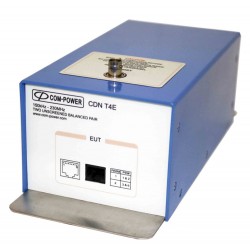
Com-Power CDN-T4E Unshielded/Unscreened Cable with 2 Balanced Conductor Pairs
-

Rent Teseq ISN T8 Impedance Stabilization Network (ISN) for Unscreened Balanced Pairs
-
Teseq ISN T8 Impedance Stabilization Network (ISN) for Unscreened Balanced Pairs
-
Dressler T4 CDN for Unshielded Symmetrical Telecom Lines 150 kHz-230 MHz
-
Monthly Rental Teseq (Schaffner) CDN T002 Coupling Network for Unshielded Balanced Pairs
-
Teseq CDN T Series Coupling Network for Unscreened Communication/Data Lines
-
Com-Power CDN-T8SE Sheilded/Screened with 4 Balanced Conductor Pairs for immunity testing
-
Com-Power CDN-T8E Unshielded/Unscreened Cable with 4 Balanced Conductor Pairs
-
Teseq CDN T8 Coupling/Decoupling Network for RJ 11, RJ45 PoE 1Gbps Testing
-
Schloder T Type Coupling/Decoupling Network, Terminal Clamps, up to 230 MHz, 150 V