
No products
Product successfully added to your shopping cart
There are 0 items in your cart. There is 1 item in your cart.
Schwarzbeck Automotive LISN
- EMC Test Equipment
- Transient Generators
- RF Power Amplifiers
- DC - 300 kHz RF Amplifiers
- 10 kHz - 250 MHz RF Amplifiers
- 10 kHz - 400 MHz RF Amplifiers
- 10 kHz - 1 GHz RF Amplifiers
- 80 MHz - 1 GHz RF Amplifiers
- 1 GHz - 2 GHz RF Amplifiers
- 700 MHz - 4.2 GHz RF Amplifiers
- 1 GHz - 6 GHz RF Amplifiers
- 2 GHz - 8 GHz RF Amplifiers
- 6 GHz - 18 GHz RF Amplifiers
- 18 GHz - 40 GHz RF Amplifiers
- Pulse Amplifiers
- RF Field Strength Probes & Meters
- RF Conducted Immunity
- EMC Receivers/EMI Analyzers
- EMC Antennas
- Coupling Decoupling Networks (CDN's)
- Line Impedance Stabilization Networks (LISN's)
- RF Test Equipment
- EMC Probes
- EMC Measurement & Equipment Software
- Power Supplies
- Electrical Safety Analyzers
- High Precision Laboratory Power Analyzers & Meters
- Anechoic Chambers
- Over-the-Air (OTA) Test Chambers
- EMI RF Shielded Tent Enclosures
- RF Shielded Rooms
- EMC Absorber
- Positioning Equipment
- EMC/EMI Test Setup
- GTEM Cells / TEM Cells
- Reverberation Chambers
- Used RF Anechoic Chambers
- EMC Chamber Filters
- EMC Chamber Shielding Gaskets
- RF Shielded Doors
- Anechoic Chamber Accessories
- Fully Anechoic (FAR) Test Chambers
- Manufacturers
- 3ctest
- AE Techron
- AH Systems
- Amplifier Research
- Boonton
- Com-Power
- Diamond Engineering
- EM Test (Ametek CTS)
- EMC Partner
- EMC Test Design
- Empower High Power RF Amplifiers
- ETS-lindgren
- Log Periodic Dipole Array Antenna
- Near Field Probe Sets
- Double Ridge Horn Antennas
- Biconical Antennas
- Quad Ridge Horn Antennas
- Electric Field Probes
- GTEM's
- Positioners & Tripods
- Loop Antennas
- Biconilog Antennas
- LISN's (Line Impedance Stabilization Network)
- Shielded Enclosures/Rooms
- Monopole Antennas
- Field Generating Antennas
- Fischer Custom Communications
- Haefely Hipotronics
- Haefely EFT/Burst Immunity Test Systems
- Haefely Surge Combination Wave Test Systems
- Haefely Surge Damped Oscillating Wave Test Systems
- Haefely Electrostatic Discharge Test Systems (ESD)
- Haefely Surge Ring Wave Test Systems
- Haefely Surge Telecom Wave Test Systems
- Haefely Magnetic Field Test Systems
- Haefely CDN's (Coupling/Decoupling Networks)
- IFI Amplifiers
- Keysight (Agilent)
- MVG - Microwave Vision Group
- PMM / Narda
- Rohde & Schwarz RF Test Equipment
- Rohde & Schwarz Broadband RF Amplifiers
- Rohde & Schwarz Spectrum Analyzers
- Rohde & Schwarz Compliant EMI Test Receivers
- Rohde & Schwarz Isotropic RF Probes
- Rohde & Schwarz RF Signal Generators
- Rohde & Schwarz RF Switches
- Rohde & Schwarz Oscilloscopes
- Rohde & Schwarz RF Power Meters
- Rohde & Schwarz RF Power Sensors
- Schloder
- Schwarzbeck Mess-Elektronik
- Schwarzbeck Antennas
- Schwarzbeck Automotive Antennas
- Schwarzbeck Broadband Horn Antennas
- Schwarzbeck Biconical Antennas
- Schwarzbeck Logarithmic Periodic Broadband Antennas
- Schwarzbeck Stacked Log-Periodic Broadband Antennas
- Schwarzbeck Biconic Log-Periodic Antennas
- Schwarzbeck Dipole Antennas
- Schwarzbeck Rod Antennas
- Schwarbeck Antenna Baluns / Holders
- Schwarzbeck LISN Line Impedance Stabilisation Networks
- Schwarbeck Decoupling & Absorbing Clamps
- Schwarzbeck Field Probes
- Schwarzbeck Helmholtz Coils
- Schwarzbeck Antenna Masts
- Schwarzbeck Coupling/Decoupling Networks
- Schwarzbeck Antennas
- Solar Electronics
- Teseq (Schaffner)
- Teseq Automotive Transient Generators
- Teseq RF Test Equipment
- Teseq EFT/Burst Generators
- Teseq RF Immunity Generators
- Teseq ESD Guns
- Teseq Surge Generators
- Teseq Harmonics & Flicker Solutions
- Teseq Dips, Interrupts & Variations Equipment
- Teseq Ring Wave Generators
- Teseq Oscillatory Waves Generators
- Teseq Absorbing Clamps / Ferrite Tube
- Teseq EMC Antennas
- Teseq Current Probes
- Teseq Coupling Networks
- Thermo Keytek
- Vicreate
- Compliance Standards
- International (IEC/EN)
- EN/IEC 61000-3-2
- EN/IEC 61000-3-3
- IEC 61000-3-11
- IEC / EN 610000-3-12
- EN/IEC 61000-4-2
- EN/IEC 61000-4-3
- EN/IEC 61000-4-4
- EN/IEC 61000-4-5
- EN/IEC 61000-4-6
- EN/IEC 61000-4-7
- EN/IEC 61000-4-8
- EN/IEC 61000-4-9
- EN/IEC 61000-4-10
- EN/IEC 61000-4-11
- EN/IEC 61000-4-12
- EN/IEC 61000-4-16
- EN/IEC 61000-4-18
- EN/IEC 61000-4-19
- EN/IEC 61000-4-20
- EN/IEC 61000-4-21
- EN/IEC 61000-4-29
- EN/IEC 61000-4-31
- IEC 61000-4-39
- EN/IEC 62132
- SEMI F47 Voltage Sag Immunity
- Product Standards
- Military & Aerospace Standards
- Automotive EMC Standards
- CISPR Standards
- Telecom Testing
- ANSI/IEEE Standards
- FCC Part 15
- FCC Part 30
- International (IEC/EN)
- Application/Test Type
- Radiated Immunity
- Bulk Current Injection Testing
- RF Emissions Testing
- Conducted Immunity
- Conducted Emissions
- Antenna Pattern Measurement
- CE Mark Testing
- Intentional Radiator Testing
- Pulsed HIRF Radar
- Over-the-Air (OTA) Testing
- 5G Test Solutions
- Automotive EMC
- SAR Measurement Equipment
- Radiated Emissions
- Battery Simulator Test Equipment
- Services
- Clearance
Viewed products
-

Schwarzbeck BAN 8508...
2 A - 8 A BAN broadband artificial...
 View larger
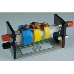
Schwarzbeck BAN 8508 Broadband Artificial Network
New
- 2 A - 8 A
- BAN broadband artificial network
- Acc. ISO 11452-7 or DC-10614
PDF Downloads
Test Equipment Description
Broadband artificial networks (BAN) are used in the automotive industry to inject radio frequency power directly into signal or power lines. This method is called “direct power injection.”
The BAN provides good isolation between the AE-port and the EuT-port. The inserted radio frequency thus is mainly directed to the EuT-port. Seen from the EuT-port the BAN provides a standard minimum impedance. The RFsignal coming from the amplifier is loaded by this impedance. Larger current BAN require larger ferrites. They have lower impedance and the decoupling is worse. For this reason the BAN 8508 should only be used I the range 2 A to 8 A. For higher or lower currents use the suitable BAN!
The basic circuit is a L/C low-pass filter. There is a broadband monolithic ceramic capacitor at the AE side. The inductance consists of five toroid core coils connected in series.
The choice of the BAN depends on the maximum current and the rate of transmission of the signal. The BAN 8508 is specified for currents between 2 A and 8 A.
The test setup and the measurement methods are described in the standard ISO 11452-7 or in manufacturer standards like DaimlerChrysler DC-10614 (2005-03).
The BAN has to be connected in series with the device under test (DuT). Therfore the 4 mm jacks can be used. For higher currents hook type cable lugs should be used because of the lower contact resistance and less heat dissipation. The red AE-connector in ISO 11452-7 called “terminal 2” is connected with the power source our auxiliary equipment.
The black binding post on the AE-side is connected to reference ground. It can be used for measurement purposes of the electrical properties of the BAN or as additional ground connection. The ground connection of the BAN is already provided by the metal sheet which builds the base of BAN 8508.
The BNC connector can be used to inject an RF signal from the generator / amplifier to the DuT. The BNC connector is also called “terminal 3” in the previously mentioned standards.
According to the standard a DC block capacitor has to be used. It has to be connected to the BNC jack and provides isolation between the DC on-board voltage and the RF-injection equipment. Thus the possibility of damaging the connected measurement equipment through the direct current from the onboard voltage is avoided. A suitable DCblock capacitor is available as option. It is called “DC-Block 500.”
For the range 8 A to 30 A the BAN 8530 is recommended. BANs for other currents or transmission rates are available on request.
The solder junction for the power line of the EuT has been defined as reference plane to measure the impedance of BAN 8508.
Security advice: The BAN 8508 has an open-frame design. Hence it has no protection against accidental contact! Depending on the operating voltage dangerous voltages could occur. Thus no conductive items may be placed on or close to the BAN. Learning about the possible dangers is a must for any user. Accidential touching of wires must be made impossible by setting up the device in a closed environment.
If the BAN is being operated with high currents for a longer period of time the coils will get hot. Only skilled personnel may use the BAN. Security standards of the country where the BAN is used have to be followed.
| Specifications | |
| Frequency range | 50 Ohm |
| Nominal range of use | 78 pF/m |
| Line type | 10 GHz |
| DuT/AE-Connector | Binding posts for 6 mm hook type cable lugs / banana jacks |
| Max. voltage line – ground | 100 V DC |
| Max. line current | 8 A DC |
| Measuring port | 50 Ω BNC |
| Max. RF-Power at BNC-Port | 5 W max. |
| Decoupling EuT or BNC to AE-Port | 0.25 MHz to 1 MHz >20 dB 1 MHz to 500 MHz >35 dB |
| Series impedance measured from EuT side | 0.25 MHz to 0.5 MHz >200 Ω 0.50 MHz to 250 MHz >500 Ω 250 MHz to 500 MHz >200 Ω |
| Dimensions W x H x D | 128 mm x 54 mm x 41 mm |
| Weight | Ca. 160 g m |
| According to | DIN ISO 11452-7: 2002-07 DC-10614, 2005-03 |
10 other products in the same category:
-
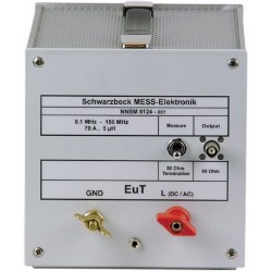
Schwarzbeck NNBM 8124 Single Path Vehicle AMN (LISN)
-
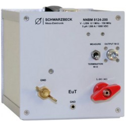
Schwarzbeck NNBM 8124-200 Single Path Vehicle AMN (LISN)
-
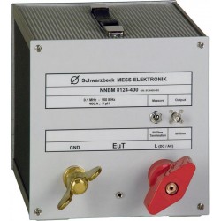
Schwarzbeck NNBM 8124-400 Single Path Vehicle AMN (LISN)
-
Schwarzbeck NNBM 8126-A 890 Single Path Airborne Equipment LISN
-
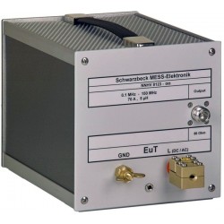
Schwarzbeck NNHV 8123 Single Path High Voltage AMN (LISN)
-
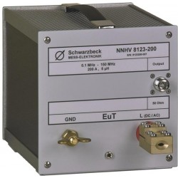
Schwarzbeck NNHV 8123-200 Single Path High Voltage AMN (LISN)
-
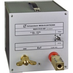
Schwarzbeck NNHV 8123-400 Single Path High Voltage AMN (LISN)
-
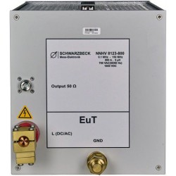
Schwarzbeck NNHV 8123-800 Single Path High Voltage AMN (LISN)
-
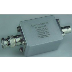
Schwarzbeck DC-Block 500 DC-Blocking Capacitor
-
Schwarzbeck BAN 8530 Broadband Artificial Network