
No products
Product successfully added to your shopping cart
There are 0 items in your cart. There is 1 item in your cart.
Schwarzbeck Logarithmic Periodic Broadband Antennas
- EMC Test Equipment
- Transient Generators
- RF Power Amplifiers
- DC - 300 kHz RF Amplifiers
- 10 kHz - 250 MHz RF Amplifiers
- 10 kHz - 400 MHz RF Amplifiers
- 10 kHz - 1 GHz RF Amplifiers
- 80 MHz - 1 GHz RF Amplifiers
- 1 GHz - 2 GHz RF Amplifiers
- 700 MHz - 4.2 GHz RF Amplifiers
- 1 GHz - 6 GHz RF Amplifiers
- 2 GHz - 8 GHz RF Amplifiers
- 6 GHz - 18 GHz RF Amplifiers
- 18 GHz - 40 GHz RF Amplifiers
- Pulse Amplifiers
- RF Field Strength Probes & Meters
- RF Conducted Immunity
- EMC Receivers/EMI Analyzers
- EMC Antennas
- Coupling Decoupling Networks (CDN's)
- Line Impedance Stabilization Networks (LISN's)
- RF Test Equipment
- EMC Probes
- EMC Measurement & Equipment Software
- Power Supplies
- Electrical Safety Analyzers
- High Precision Laboratory Power Analyzers & Meters
- Anechoic Chambers
- Over-the-Air (OTA) Test Chambers
- EMI RF Shielded Tent Enclosures
- RF Shielded Rooms
- EMC Absorber
- Positioning Equipment
- EMC/EMI Test Setup
- GTEM Cells / TEM Cells
- Reverberation Chambers
- Used RF Anechoic Chambers
- EMC Chamber Filters
- EMC Chamber Shielding Gaskets
- RF Shielded Doors
- Anechoic Chamber Accessories
- Fully Anechoic (FAR) Test Chambers
- Manufacturers
- 3ctest
- AE Techron
- AH Systems
- Amplifier Research
- Boonton
- Com-Power
- Diamond Engineering
- EM Test (Ametek CTS)
- EMC Partner
- EMC Test Design
- Empower High Power RF Amplifiers
- ETS-lindgren
- Log Periodic Dipole Array Antenna
- Near Field Probe Sets
- Double Ridge Horn Antennas
- Biconical Antennas
- Quad Ridge Horn Antennas
- Electric Field Probes
- GTEM's
- Positioners & Tripods
- Loop Antennas
- Biconilog Antennas
- LISN's (Line Impedance Stabilization Network)
- Shielded Enclosures/Rooms
- Monopole Antennas
- Field Generating Antennas
- Fischer Custom Communications
- Haefely Hipotronics
- Haefely EFT/Burst Immunity Test Systems
- Haefely Surge Combination Wave Test Systems
- Haefely Surge Damped Oscillating Wave Test Systems
- Haefely Electrostatic Discharge Test Systems (ESD)
- Haefely Surge Ring Wave Test Systems
- Haefely Surge Telecom Wave Test Systems
- Haefely Magnetic Field Test Systems
- Haefely CDN's (Coupling/Decoupling Networks)
- IFI Amplifiers
- Keysight (Agilent)
- MVG - Microwave Vision Group
- PMM / Narda
- Rohde & Schwarz RF Test Equipment
- Rohde & Schwarz Broadband RF Amplifiers
- Rohde & Schwarz Spectrum Analyzers
- Rohde & Schwarz Compliant EMI Test Receivers
- Rohde & Schwarz Isotropic RF Probes
- Rohde & Schwarz RF Signal Generators
- Rohde & Schwarz RF Switches
- Rohde & Schwarz Oscilloscopes
- Rohde & Schwarz RF Power Meters
- Rohde & Schwarz RF Power Sensors
- Schloder
- Schwarzbeck Mess-Elektronik
- Schwarzbeck Antennas
- Schwarzbeck Automotive Antennas
- Schwarzbeck Broadband Horn Antennas
- Schwarzbeck Biconical Antennas
- Schwarzbeck Logarithmic Periodic Broadband Antennas
- Schwarzbeck Stacked Log-Periodic Broadband Antennas
- Schwarzbeck Biconic Log-Periodic Antennas
- Schwarzbeck Dipole Antennas
- Schwarzbeck Rod Antennas
- Schwarbeck Antenna Baluns / Holders
- Schwarzbeck LISN Line Impedance Stabilisation Networks
- Schwarbeck Decoupling & Absorbing Clamps
- Schwarzbeck Field Probes
- Schwarzbeck Helmholtz Coils
- Schwarzbeck Antenna Masts
- Schwarzbeck Coupling/Decoupling Networks
- Schwarzbeck Antennas
- Solar Electronics
- Teseq (Schaffner)
- Teseq Automotive Transient Generators
- Teseq RF Test Equipment
- Teseq EFT/Burst Generators
- Teseq RF Immunity Generators
- Teseq ESD Guns
- Teseq Surge Generators
- Teseq Harmonics & Flicker Solutions
- Teseq Dips, Interrupts & Variations Equipment
- Teseq Ring Wave Generators
- Teseq Oscillatory Waves Generators
- Teseq Absorbing Clamps / Ferrite Tube
- Teseq EMC Antennas
- Teseq Current Probes
- Teseq Coupling Networks
- Thermo Keytek
- Vicreate
- Compliance Standards
- International (IEC/EN)
- EN/IEC 61000-3-2
- EN/IEC 61000-3-3
- IEC 61000-3-11
- IEC / EN 610000-3-12
- EN/IEC 61000-4-2
- EN/IEC 61000-4-3
- EN/IEC 61000-4-4
- EN/IEC 61000-4-5
- EN/IEC 61000-4-6
- EN/IEC 61000-4-7
- EN/IEC 61000-4-8
- EN/IEC 61000-4-9
- EN/IEC 61000-4-10
- EN/IEC 61000-4-11
- EN/IEC 61000-4-12
- EN/IEC 61000-4-16
- EN/IEC 61000-4-18
- EN/IEC 61000-4-19
- EN/IEC 61000-4-20
- EN/IEC 61000-4-21
- EN/IEC 61000-4-29
- EN/IEC 61000-4-31
- IEC 61000-4-39
- EN/IEC 62132
- SEMI F47 Voltage Sag Immunity
- Product Standards
- Military & Aerospace Standards
- Automotive EMC Standards
- CISPR Standards
- Telecom Testing
- ANSI/IEEE Standards
- FCC Part 15
- FCC Part 30
- International (IEC/EN)
- Application/Test Type
- Radiated Immunity
- Bulk Current Injection Testing
- RF Emissions Testing
- Conducted Immunity
- Conducted Emissions
- Antenna Pattern Measurement
- CE Mark Testing
- Intentional Radiator Testing
- Pulsed HIRF Radar
- Over-the-Air (OTA) Testing
- 5G Test Solutions
- Automotive EMC
- SAR Measurement Equipment
- Radiated Emissions
- Battery Simulator Test Equipment
- Services
- Clearance
Viewed products
-

Schwarzbeck XSLP 9143...
300 MHz - 3(5.5) GHz Max 50W input...
-

Amplifier Research...
20 - 1000 MHz (Interfaces not...
 View larger
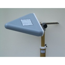
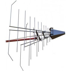
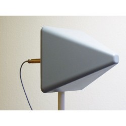
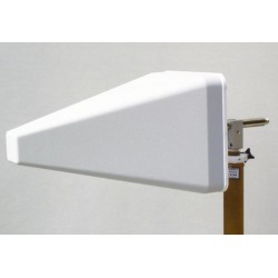
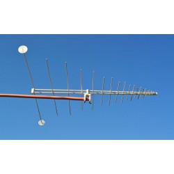
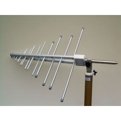
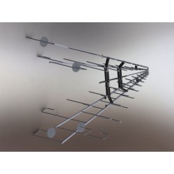
Schwarzbeck XSLP 9143 Dual Polarized LPDA
New
- 300 MHz - 3(5.5) GHz
- Max 50W input Typ.gain 9dBi
- Dual-Polarized Log Periodic Antenna
In Stock
PDF Downloads
Test Equipment Description

Assignment of Polarisation Planes
The XSLP 9143 has two orthogonal polarisation planes, which can be accessed independantly via N-connectors. The assignment of the Nconnector to the corresponding polarisation plane is shown in the above picture. The Inner conductor of the N-connector stands always perpendicular on the corresponding polarisation plane. Example: Connector "B" should be used for horizontal polarisation. The antenna is rotated around its longitudinal axis until the elements assigned with "B" are horizontal. The connector "B" faces either upwards or towards ground.
Decoupling of the Polarisation Planes
Although the two polarisation planes are exactly orthogonal to each other, there is no 100% decoupling between them. A horizontal polarised field contributes also to the indication of the vertical polarised antenna section, but with reduced effect. Typical decoupling values for the cross polarised fieldstrength indication are 15 to 20 dB. The decoupling of the polarisation planes depends a lot on environmental reflections. Best decoupling results can be achieved under free-space conditions. The cross polarisation decoupling decreases at higher frequencies due to the element displacement at the antenna tip, which approaches to the element length itself.
Equality of Polarisation Planes
Small differences between the polarisation planes are recognizable for construction reasons. The feeding point distance to the active element is somewhat different. Normally the deviations between the planes are less than 1 dB, as worst case 1.5 dB difference can be assumed. Especially at higher frequencies and for best accuracy it is recommended to use the data which is explicitly assigned to the respective polarisation plane (Sections A or B).
General Hints
For highest accuracy requirements a suitable fixed attenuator (3 dB to 10 dB) may be useful under certain circumstances. Inserting a fixed attenuator at the antenna terminal improves impedance matching, but also reduces the gain and increases the antenna factor by the attenuation value. With an SWR < 2 the attenuator may be omitted in most applications. Antenna measurements in the microwave frequency range suffer from environmental reflections, which may even occur at nonmetallic surfaces as e.g. plastic. Therefore it is recommended to avoid large mast adapters and other big parts in the near surrounding of the antenna.
Antenna reference point
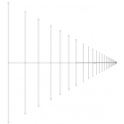
The phase center was used as antenna reference point during calibration. The phase center position is located near the element in half-wave resonance. Example: The wavelength at 1 GHz is 30 cm, the corresponding element would be 15 cm long (the location of the phase center is the approx. 12.5 cm behind the antenna tip)
Further Antenna Data
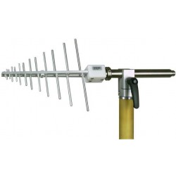
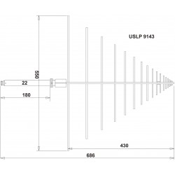
The XSLP 9143 is directly derived from the very popular model USLP 9143. Therefore pattern data, fieldstrength generation data and correction for short measuring distances of the USLP 9143 can be used.
| Specifications | ||
| Type | Linear dual polarized Logarithmic Periodic Broadband Antenna (Aluminium tubing) for Receive and Transmit Applications. | |
| Nominal Frequency Range | 300 MHz. ... 3 GHz | |
| Usable Frequency Range | 250 MHz ... 5.5 GHz | |
| Isotropic Gain | typ.: 4 ... 7 dBi | |
| Antenna Factor | 15 ... 35 ( 42) dB/m | |
| Nominal Impedance | 50 W | |
| Standing Wave Ratio SWR typical | 1.5 - 3 | |
| Front to Back Ratio | > 15 dB | |
| Cross Polarisation Rejection | typ. 15-25 dB | |
| 3 dB Beamwidth typ. (E-Plane) | 50°-80° | |
| 3 dB Beamwidth typ. (H-Plane) | 90°-170° | |
| Max. Input Power | 100 W (intermitt.) 50 W (cont.) | |
| N-Connectors Female | ||
| Mount | 22 mm Tube, Indexing Ring | |
| Width x Length x Thickness | 540 x 695 x 540 mm | |
| Weight | 1.2 kg | |
14 other products in the same category:
-
Schwarzbeck ESLP 9145 Microwave Log Periodic Antenna
-
Schwarzbeck USLP 9142 UHF-SHF Broadband Log.-Per. Antenna
-
Schwarzbeck USLP 9143 UHF-SHF Log. - Per. Broadband Antenna
-
Schwarzbeck STLP 9129 Stacked Logarithmic Periodic Antenna
-
Schwarzbeck STLP 9148 Microwave Logarithmic Periodic Antenna
-
Schwarzbeck STLP 9149 Microwave Logarithmic Periodic Antenna
-
Schwarzbeck UHALP 9108 A Log Periodic Antenna
-
Schwarzbeck VULP 9118 A Log Periodic Antenna
-
Schwarzbeck VULP 9118 G Log Periodic Antenna
-
Schwarzbeck VULP 9118 H Log Periodic Antenna
-
Schwarzbeck VUSLP 9111 Log Periodic Antenna
-
Schwarzbeck STLP 9128 C Stacked Log Periodic Antenna
-
Schwarzbeck STLP 9128 E Special - Stacked Log Periodic Antenna
-

Schwarzbeck VULP 9118 B Log Periodic Antenna