
No products
Product successfully added to your shopping cart
There are 0 items in your cart. There is 1 item in your cart.
Schwarzbeck Special LISN's
- EMC Test Equipment
- Transient Generators
- RF Power Amplifiers
- DC - 300 kHz RF Amplifiers
- 10 kHz - 250 MHz RF Amplifiers
- 10 kHz - 400 MHz RF Amplifiers
- 10 kHz - 1 GHz RF Amplifiers
- 80 MHz - 1 GHz RF Amplifiers
- 1 GHz - 2 GHz RF Amplifiers
- 700 MHz - 4.2 GHz RF Amplifiers
- 1 GHz - 6 GHz RF Amplifiers
- 2 GHz - 8 GHz RF Amplifiers
- 6 GHz - 18 GHz RF Amplifiers
- 18 GHz - 40 GHz RF Amplifiers
- Pulse Amplifiers
- RF Field Strength Probes & Meters
- RF Conducted Immunity
- EMC Receivers/EMI Analyzers
- EMC Antennas
- Coupling Decoupling Networks (CDN's)
- Line Impedance Stabilization Networks (LISN's)
- RF Test Equipment
- EMC Probes
- EMC Measurement & Equipment Software
- Power Supplies
- Electrical Safety Analyzers
- High Precision Laboratory Power Analyzers & Meters
- Anechoic Chambers
- Over-the-Air (OTA) Test Chambers
- EMI RF Shielded Tent Enclosures
- RF Shielded Rooms
- EMC Absorber
- Positioning Equipment
- EMC/EMI Test Setup
- GTEM Cells / TEM Cells
- Reverberation Chambers
- Used RF Anechoic Chambers
- EMC Chamber Filters
- EMC Chamber Shielding Gaskets
- RF Shielded Doors
- Anechoic Chamber Accessories
- Fully Anechoic (FAR) Test Chambers
- Manufacturers
- 3ctest
- AE Techron
- AH Systems
- Amplifier Research
- Boonton
- Com-Power
- Diamond Engineering
- EM Test (Ametek CTS)
- EMC Partner
- EMC Test Design
- Empower High Power RF Amplifiers
- ETS-lindgren
- Log Periodic Dipole Array Antenna
- Near Field Probe Sets
- Double Ridge Horn Antennas
- Biconical Antennas
- Quad Ridge Horn Antennas
- Electric Field Probes
- GTEM's
- Positioners & Tripods
- Loop Antennas
- Biconilog Antennas
- LISN's (Line Impedance Stabilization Network)
- Shielded Enclosures/Rooms
- Monopole Antennas
- Field Generating Antennas
- Fischer Custom Communications
- Haefely Hipotronics
- Haefely EFT/Burst Immunity Test Systems
- Haefely Surge Combination Wave Test Systems
- Haefely Surge Damped Oscillating Wave Test Systems
- Haefely Electrostatic Discharge Test Systems (ESD)
- Haefely Surge Ring Wave Test Systems
- Haefely Surge Telecom Wave Test Systems
- Haefely Magnetic Field Test Systems
- Haefely CDN's (Coupling/Decoupling Networks)
- IFI Amplifiers
- Keysight (Agilent)
- MVG - Microwave Vision Group
- PMM / Narda
- Rohde & Schwarz RF Test Equipment
- Rohde & Schwarz Broadband RF Amplifiers
- Rohde & Schwarz Spectrum Analyzers
- Rohde & Schwarz Compliant EMI Test Receivers
- Rohde & Schwarz Isotropic RF Probes
- Rohde & Schwarz RF Signal Generators
- Rohde & Schwarz RF Switches
- Rohde & Schwarz Oscilloscopes
- Rohde & Schwarz RF Power Meters
- Rohde & Schwarz RF Power Sensors
- Schloder
- Schwarzbeck Mess-Elektronik
- Schwarzbeck Antennas
- Schwarzbeck Automotive Antennas
- Schwarzbeck Broadband Horn Antennas
- Schwarzbeck Biconical Antennas
- Schwarzbeck Logarithmic Periodic Broadband Antennas
- Schwarzbeck Stacked Log-Periodic Broadband Antennas
- Schwarzbeck Biconic Log-Periodic Antennas
- Schwarzbeck Dipole Antennas
- Schwarzbeck Rod Antennas
- Schwarbeck Antenna Baluns / Holders
- Schwarzbeck LISN Line Impedance Stabilisation Networks
- Schwarbeck Decoupling & Absorbing Clamps
- Schwarzbeck Field Probes
- Schwarzbeck Helmholtz Coils
- Schwarzbeck Antenna Masts
- Schwarzbeck Coupling/Decoupling Networks
- Schwarzbeck Antennas
- Solar Electronics
- Teseq (Schaffner)
- Teseq Automotive Transient Generators
- Teseq RF Test Equipment
- Teseq EFT/Burst Generators
- Teseq RF Immunity Generators
- Teseq ESD Guns
- Teseq Surge Generators
- Teseq Harmonics & Flicker Solutions
- Teseq Dips, Interrupts & Variations Equipment
- Teseq Ring Wave Generators
- Teseq Oscillatory Waves Generators
- Teseq Absorbing Clamps / Ferrite Tube
- Teseq EMC Antennas
- Teseq Current Probes
- Teseq Coupling Networks
- Thermo Keytek
- Vicreate
- Compliance Standards
- International (IEC/EN)
- EN/IEC 61000-3-2
- EN/IEC 61000-3-3
- IEC 61000-3-11
- IEC / EN 610000-3-12
- EN/IEC 61000-4-2
- EN/IEC 61000-4-3
- EN/IEC 61000-4-4
- EN/IEC 61000-4-5
- EN/IEC 61000-4-6
- EN/IEC 61000-4-7
- EN/IEC 61000-4-8
- EN/IEC 61000-4-9
- EN/IEC 61000-4-10
- EN/IEC 61000-4-11
- EN/IEC 61000-4-12
- EN/IEC 61000-4-16
- EN/IEC 61000-4-18
- EN/IEC 61000-4-19
- EN/IEC 61000-4-20
- EN/IEC 61000-4-21
- EN/IEC 61000-4-29
- EN/IEC 61000-4-31
- IEC 61000-4-39
- EN/IEC 62132
- SEMI F47 Voltage Sag Immunity
- Product Standards
- Military & Aerospace Standards
- Automotive EMC Standards
- CISPR Standards
- Telecom Testing
- ANSI/IEEE Standards
- FCC Part 15
- FCC Part 30
- International (IEC/EN)
- Application/Test Type
- Radiated Immunity
- Bulk Current Injection Testing
- RF Emissions Testing
- Conducted Immunity
- Conducted Emissions
- Antenna Pattern Measurement
- CE Mark Testing
- Intentional Radiator Testing
- Pulsed HIRF Radar
- Over-the-Air (OTA) Testing
- 5G Test Solutions
- Automotive EMC
- SAR Measurement Equipment
- Radiated Emissions
- Battery Simulator Test Equipment
- Services
- Clearance
Viewed products
-

Schwarzbeck PVDC 8300...
PV LISN 1500 V 50 A Common Mode...
") View larger
View larger ")
Schwarzbeck PVDC 8300 DC AMN (LISN)
New
- PV LISN
- 1500 V
- 50 A
- Common Mode Impedance 150 Ohm
- Z differential mode = 100 Ohm
- air coils 280 microhenry
- PVDC 8300 Opt. Fans
- Fans for a maximum continuous current of 100 A
PDF Downloads
Test Equipment Description
The symmetric DC-LISN PVDC 8300 can be used for measuring the disturbance voltage in the frequency range from 0.15 MHz to 30 MHz on photovoltaic inverters.
Up to now the conducted emissions of photovoltaic inverters at the mains terminals were usually measured using LISN according to CISPR 16-1- 2. The circuit concepts of PV-inverters may cause ripple currents on the DC-side of the inverter, though. These ripple currents, which mostly are in direct proportion to the mains frequency, are passing through the cabling and the PV-generator modules and can be radiated as magnetic fields with sometimes remarkable disturbance effect. Traditional measurements at the PV-inverters' AC terminals will not be able to reveal such disturbance phenomena.
The PVDC 8300 was especially designed to measure all kinds of disturbance voltages at the DC-side of photovoltaic inverters. These are in detail the disturbance voltage of one conductor above reference ground (unsymmetrical disturbance voltage), the common mode disturbance volage of a pair of conductors above ground (asymmetrical disturbance voltage) and finally, the differential mode voltage between two conductors.
The conducted emissions of photovoltaic inverters at the mains terminals are usually measured using LISN according to CISPR 16- 1-2. The circuit concepts of PV-inverters may cause ripple currents on the DC-side of the inverter. These ripple currents are passing through the cabling and the PV-generator modules and can be radiated as magnetic fields with sometimes remarkable disturbance effect. Traditional measurements at the PVinverters' AC terminals will not be able to reveal such disturbance phenomena. The PVDC 8300 was especially designed to measure all kinds of disturbance voltages at the DC-side of photovoltaic inverters. These are in detail the disturbance voltage of one conductor above reference ground (unsymmetrical disturbance voltage), the common mode disturbance voltage of a pair of conductors above ground (asymmetrical disturbance voltage) and finally, the differential mode voltage between two conductors.
Application
The symmetric DC-LISN PVDC 8300 can be used for measuring of the disturbance voltage in the frequency range from 0.15 MHz to 30 MHz on photovoltaic inverters. It is designed with air-core or iron-free inductors to prevent intermodulation. The permitted continuous current is 100 A with activated fans. Without fans 50 A continuous current can be supplied. Short time currents over 150 A can be applied. The temperature of the built in inductors may not exceed 150°C. The device under test is connected to the wing terminals of the front panel. The PV-generator or the PV-simulator is connected to the rear side.
The capacitor C3 was limited to 0.22 µF to avoid possible malfunction of the EuT. This leads to a differential mode decoupling of more than 20 dB. If higher decoupling values are required (e.g. 40 dB or more), the use of an additional 1 µF / 1500 V DC capacitor at the AE-terminals will bring significant improvements.
Interference Voltage measurements
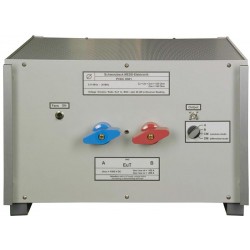
The photovoltaic generator or simulator must be connected to the rear side (AE) of the PVDC 8300. The device under test (EUT) i.e. the DC input of a PV-inverter is connected to the terminals at the front panel. The RF interference voltage emitted by the DC-side of the inverter is measured at the ‘output’ BNC jack where it can be connected to a 50 Ω EMI receiver. The switch on the front panel must be set to „DM differential mode“, „CM common mode“, „A“, or „B“ depending on the wished measurement mode.
Mode A or mode B: The unsymmetrical interference voltage is measured from port „A“ or „B“ to RF-ground (V-LISN). Common mode (CM): The sum of interference voltage of port „A“ and „B“ is measured against RF ground (T-LISN, asymmetrical disturbance voltage). In these three modes of measurement the input impedance seen from the device under test is 150 Ω. Differential mode (DM): The symmetrical disturbance voltage between the terminals „A“ und „B“ is measured (Delta LISN). The impedance here is 100 Ω.
The RF ground potential is connected with the GND connector or with the aluminium bars on the rear panel.
Notice: In any case, ground-connect LISN before connecting to power line. Precise safety instructions must be provided to any user of the LISN. Inappropriate usage of the LISN may cause deadly injuries!
Always switch off supply voltage before connecting or disconnecting terminals. An easily accessible circuit breaker before and behind the LISN is a must! The capacitors of the LISN can store charge over a short time, even if the LISN is completely disconnected from power supplies and EuT. We recommend to discharge the capacitors using an isolated cable to ground before touching the terminals. The discharge-resistors from “A” or “B” to “GND” are 1.5 MΩ, because the majority of GCPC (Grid Connected Power Conditioner) are testing several isolation conditions during start up.
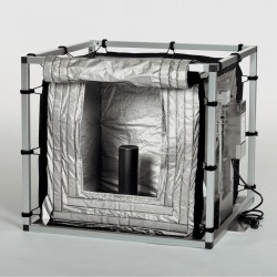
Air circulation must be possible at any time. Neither the top side nor the bottom side of the LISN may be covered during operation!
| Schwarzbeck PVDC 8300 Specifications | ||
| Frequency Range | 0.15 MHz - 30 MHz | |
| Max. cont. current | 100 A | |
| Max. current (limited time, 15 min) | 150 A | |
| Max. Voltage (DC) | 1500 V | |
| Common Mode Impedance (Mode switch CM, A or B) | (150 +/- 20) Ω | |
| Differential Mode Impedance (Mode switch DM) | (150 +/- 20) Ω | |
| Phase at EUT-Terminals | (0 +/- 40)° | |
| Insertion loss (EUT - AE) | >20 dB | |
| Longitudinal conversion loss LCL | >20 dB | |
| Voltage Division Factor at the measuring port | (20 +/- 2) dB (10:1) | |
| Resistance (DC) with feed terminals shorted (T=25°C) | 90 mΩ | |
| EUT Connectors | Wing terminals | |
| Dimensions(W x H x D) | 448 x 191 x 470 mm | |
| Weight | 15 kg | |
Associated EMC Test Equipment

7 other products in the same category:
-
Schwarzbeck PVDC 8301 DC-AMN (LISN)
-
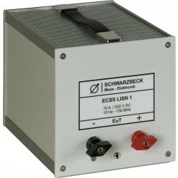
Schwarzbeck ECSS LISN 1 Double Path AMN (LISN)
-

Schwarzbeck ECSS LISN 2 Double Path AMN (LISN)
-
Schwarzbeck ECSS LISN 2 - 75A Double Path AMN (LISN)
-
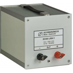
Schwarzbeck ECSS LISN 3 Double Path AMN (LISN)
-
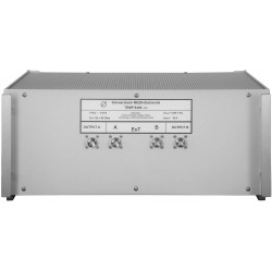
Schwarzbeck TEMP 8400 Tempest AMN (LISN)
-
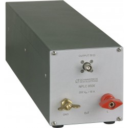
Schwarzbeck NPLC 8500 Line Impedance Stabilization Network