
No products
Product successfully added to your shopping cart
There are 0 items in your cart. There is 1 item in your cart.
AF-Series
- EMC Test Equipment
- Transient Generators
- RF Power Amplifiers
- DC - 300 kHz RF Amplifiers
- 10 kHz - 250 MHz RF Amplifiers
- 10 kHz - 400 MHz RF Amplifiers
- 10 kHz - 1 GHz RF Amplifiers
- 80 MHz - 1 GHz RF Amplifiers
- 1 GHz - 2 GHz RF Amplifiers
- 700 MHz - 4.2 GHz RF Amplifiers
- 1 GHz - 6 GHz RF Amplifiers
- 2 GHz - 8 GHz RF Amplifiers
- 6 GHz - 18 GHz RF Amplifiers
- 18 GHz - 40 GHz RF Amplifiers
- Pulse Amplifiers
- RF Field Strength Probes & Meters
- RF Conducted Immunity
- EMC Receivers/EMI Analyzers
- EMC Antennas
- Coupling Decoupling Networks (CDN's)
- Line Impedance Stabilization Networks (LISN's)
- RF Test Equipment
- EMC Probes
- EMC Measurement & Equipment Software
- Power Supplies
- Electrical Safety Analyzers
- High Precision Laboratory Power Analyzers & Meters
- Anechoic Chambers
- Over-the-Air (OTA) Test Chambers
- EMI RF Shielded Tent Enclosures
- RF Shielded Rooms
- EMC Absorber
- Positioning Equipment
- EMC/EMI Test Setup
- GTEM Cells / TEM Cells
- Reverberation Chambers
- Used RF Anechoic Chambers
- EMC Chamber Filters
- EMC Chamber Shielding Gaskets
- RF Shielded Doors
- Anechoic Chamber Accessories
- Fully Anechoic (FAR) Test Chambers
- Manufacturers
- 3ctest
- AE Techron
- AH Systems
- Amplifier Research
- Boonton
- Com-Power
- Diamond Engineering
- EM Test (Ametek CTS)
- EMC Partner
- EMC Test Design
- Empower High Power RF Amplifiers
- ETS-lindgren
- Log Periodic Dipole Array Antenna
- Near Field Probe Sets
- Double Ridge Horn Antennas
- Biconical Antennas
- Quad Ridge Horn Antennas
- Electric Field Probes
- GTEM's
- Positioners & Tripods
- Loop Antennas
- Biconilog Antennas
- LISN's (Line Impedance Stabilization Network)
- Shielded Enclosures/Rooms
- Monopole Antennas
- Field Generating Antennas
- Fischer Custom Communications
- Haefely Hipotronics
- Haefely EFT/Burst Immunity Test Systems
- Haefely Surge Combination Wave Test Systems
- Haefely Surge Damped Oscillating Wave Test Systems
- Haefely Electrostatic Discharge Test Systems (ESD)
- Haefely Surge Ring Wave Test Systems
- Haefely Surge Telecom Wave Test Systems
- Haefely Magnetic Field Test Systems
- Haefely CDN's (Coupling/Decoupling Networks)
- IFI Amplifiers
- Keysight (Agilent)
- MVG - Microwave Vision Group
- PMM / Narda
- Rohde & Schwarz RF Test Equipment
- Rohde & Schwarz Broadband RF Amplifiers
- Rohde & Schwarz Spectrum Analyzers
- Rohde & Schwarz Compliant EMI Test Receivers
- Rohde & Schwarz Isotropic RF Probes
- Rohde & Schwarz RF Signal Generators
- Rohde & Schwarz RF Switches
- Rohde & Schwarz Oscilloscopes
- Rohde & Schwarz RF Power Meters
- Rohde & Schwarz RF Power Sensors
- Schloder
- Schwarzbeck Mess-Elektronik
- Schwarzbeck Antennas
- Schwarzbeck Automotive Antennas
- Schwarzbeck Broadband Horn Antennas
- Schwarzbeck Biconical Antennas
- Schwarzbeck Logarithmic Periodic Broadband Antennas
- Schwarzbeck Stacked Log-Periodic Broadband Antennas
- Schwarzbeck Biconic Log-Periodic Antennas
- Schwarzbeck Dipole Antennas
- Schwarzbeck Rod Antennas
- Schwarbeck Antenna Baluns / Holders
- Schwarzbeck LISN Line Impedance Stabilisation Networks
- Schwarbeck Decoupling & Absorbing Clamps
- Schwarzbeck Field Probes
- Schwarzbeck Helmholtz Coils
- Schwarzbeck Antenna Masts
- Schwarzbeck Coupling/Decoupling Networks
- Schwarzbeck Antennas
- Solar Electronics
- Teseq (Schaffner)
- Teseq Automotive Transient Generators
- Teseq RF Test Equipment
- Teseq EFT/Burst Generators
- Teseq RF Immunity Generators
- Teseq ESD Guns
- Teseq Surge Generators
- Teseq Harmonics & Flicker Solutions
- Teseq Dips, Interrupts & Variations Equipment
- Teseq Ring Wave Generators
- Teseq Oscillatory Waves Generators
- Teseq Absorbing Clamps / Ferrite Tube
- Teseq EMC Antennas
- Teseq Current Probes
- Teseq Coupling Networks
- Thermo Keytek
- Vicreate
- Compliance Standards
- International (IEC/EN)
- EN/IEC 61000-3-2
- EN/IEC 61000-3-3
- IEC 61000-3-11
- IEC / EN 610000-3-12
- EN/IEC 61000-4-2
- EN/IEC 61000-4-3
- EN/IEC 61000-4-4
- EN/IEC 61000-4-5
- EN/IEC 61000-4-6
- EN/IEC 61000-4-7
- EN/IEC 61000-4-8
- EN/IEC 61000-4-9
- EN/IEC 61000-4-10
- EN/IEC 61000-4-11
- EN/IEC 61000-4-12
- EN/IEC 61000-4-16
- EN/IEC 61000-4-18
- EN/IEC 61000-4-19
- EN/IEC 61000-4-20
- EN/IEC 61000-4-21
- EN/IEC 61000-4-29
- EN/IEC 61000-4-31
- IEC 61000-4-39
- EN/IEC 62132
- SEMI F47 Voltage Sag Immunity
- Product Standards
- Military & Aerospace Standards
- Automotive EMC Standards
- CISPR Standards
- Telecom Testing
- ANSI/IEEE Standards
- FCC Part 15
- FCC Part 30
- International (IEC/EN)
- Application/Test Type
- Radiated Immunity
- Bulk Current Injection Testing
- RF Emissions Testing
- Conducted Immunity
- Conducted Emissions
- Antenna Pattern Measurement
- CE Mark Testing
- Intentional Radiator Testing
- Pulsed HIRF Radar
- Over-the-Air (OTA) Testing
- 5G Test Solutions
- Automotive EMC
- SAR Measurement Equipment
- Radiated Emissions
- Battery Simulator Test Equipment
- Services
- Clearance
Viewed products
-

Schwarzbeck CDNE M2...
30 MHz – 300 MHz 2 Unshielded Mains...
-

Schwarzbeck CDNE M3...
30 MHz – 300 MHz 3 Unshielded Mains...
 View larger
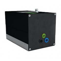
Schwarzbeck CDNE M2 Coupling Decoupling Network
New
- 30 MHz – 300 MHz
- 2 Unshielded Mains Lines
- CDNE with Tight Tolerances
- For CISPR 15 Emission Measurements
- With 2 Mains Conductors can also be used as CDNE AF2.
PDF Downloads
Test Equipment Description
CDNs have been used as coupling- /decoupling networks to measure conducted noise as well as for immunity testing so far. Contrary to the couple-/decouple networks (CDN) described in IEC/EN 61000-4-6 the category of CDNE has been created especially for the measurement of emissions of luminaries featuring tighter tolerance.
Attention! The CDNE is not appropriate for measuring immunity!
in EN 55015. The tolerances of the asymmetric impedance became tighter. The tolerance for the voltage division factor is now defined constantly over the whole frequency range and a new requirement for a defined symmetrical impedance has been introduced for the frequency range 30 MHz to 300 MHz.
For measurements on DuTs without PE one has to use the CDNE M2. For measurements using PE,N and L the CDNE M3 has to be used.
The interference voltage emitted by the device under test can be measured at the BNC jack of the measurement port. The voltage division factor to this port is 20 dB.
Due to the current-compensated coils within the CDNE it is ensured that there is a minimum decoupling of at least 30 dB between EuT and AE. Noise coming from the mains side is thus well kept away for the measurement.
The connection to ground can be accomplished using the ground plane of the CDNE. Additionally there is a M4 thread located at the AE side to ground as well as a 4 mm socket to connect the device to ground.
To improve the operational safety the mains voltage-carrying connections are carried out as security sockets. We recommend to use special 4 mm security plugs if you plan to design your own adapters. Those connectors can be purchased optionally.
To verify the CDNE some measurements require a common mode potential. The common mode reference point is defined for CDNE devices for unshielded cables as the short-circuiting point of all wires.
To be able to measure at the herein before mentioned point to check the standard values of the CDNE (i.e. common mode impedance, voltage division factor) a low-inductance and lowresistance short circuit jumper is required.
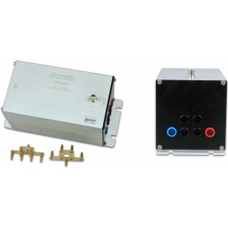
This adapter is available optionally. It consists of two parts. There is a shortcircuit bridge (CA CDNE M2 Part A) and an adapter kit (CA CDNE Part B).
 CA CDNE M2 Part A |  CA CDNE Part B |
Warning! Under no circumstances the short-circuit jumper may be used while AE is connected to mains!
One of the most important characteristics of the CDNE is the coupling attenuation between the EuT port and the BNC measurement port (other expressions: correction or Voltage Division Factor VDF). This attenuation is recorded for each device and is part of the calibration certificate. If the coupling attenuation is supposed to be calibrated in the real emission measurement setup a serial resistance of 100 Ω is needed to adapt the 150 Ω of the CDNE to the 50°Ω measurement system. For this purpose we offer the optionally available adapter SR100-6W.
There is a resistive attenuator built in the BNC output to force a match. According to the standard CISPR/A/944/CD Fig. J2 a value bigger than 6 dB is demanded. By design the internal circuit has an attenuation of 9.5 dB. Together with the built in attenuator of 10.5 dB this results in a total attenuation of 20 dB. Thus the measurement port matches the 50 Ω very well and supersedes an external attenuator.

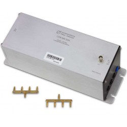
Abb. 2 Serienwiderstand SR-100-6W
Series resistor SR-100-6W
The dual pole side of CA CDNE M2 (part A & B) has to be connected to the EuT port of the CDNE. The single pole 4 mm jack can be plugged into the EuT port of the SR100-6W. Due to the length of the CA CDN M2 part B the distance between the CDNE M2 and the SR100-6W is automatically set to 30 mm as described in the standard.
For the emission measurement acc. CISPR 15 the adapters are not required as data for the voltage division factor (correction) is automatically delivered. The adapters however are recommendable for a quick performance check or a calibration of the CDNE.

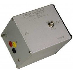
Abb. 3 CDNE M2 mit SR-100-6W und Adapter
CDNE M2 with SR-100-6W and adapters
| Specifications | |
| Frequency range | 30 MHz – 300 MHz |
| Line type | 2 unshielded mains lines |
| Connector for EuT and AE | 2x4 mm safety laboratory jacks |
| Measurement port | 50 Ω BNC |
| Max. voltage line to ground | 400 VDC 277 VAC 50/60 Hz |
| Max. current | 16 A |
| Common Mode Impedance | 140 dBµV |
| Max. voltage measuring port | 5 V |
| Voltage division factor EuT – measuring port | 20 dB ±1.5 dB |
| Decoupling attenuation EuT – AE | >30 dB |
| Ground connection | 4 mm laboratory jack and M4 screw at AE side |
| Dimensions W x H x D | 104 mm x 104 mm x 127 mm |
| Weight | ~800 g |
| Circuit | CISPR/A/944/CD, Fig. J2 |
| Acc. to standard | CISPR 15/ EN 55015 |
16 other products in the same category:
-
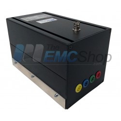
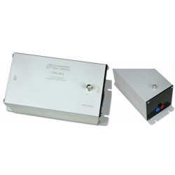
Dressler AF4 Coupling/Decoupling Networks (CDN) 150 kHz-230 MHz
-
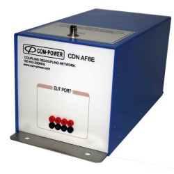
Com-Power CDN-AF8E 150kHz - 230MHz Coupling Network Eight Wire Unscreened, Unbalanced Cables
-
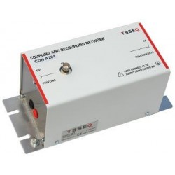
Teseq CDN AF Series Coupling/Decoupling Network for Unscreened/Unbalanced Lines
-
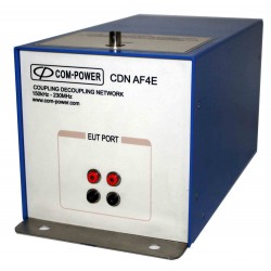
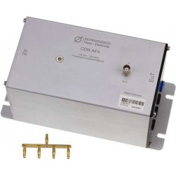
Com-Power CDN-AF4E 150kHz - 230MHz Coupling Network Four Wire Unscreened, Unbalanced Cables
-
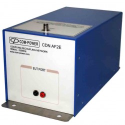
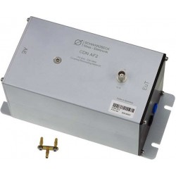
Com-Power CDN-AF2E 150kHz - 230MHz Coupling Network Two Wire Unscreened, Unbalanced Cables
-
EM Test (Lüthi) AF-Type Coupling/Decoupling Network for Unscreened/Unsymmetrical Lines
-
Fischer Custom Communications FCC-801-AF3, 3-Line, CDN for IEC 61000-4-6 Conducted Immunity
-
Schloder AF Type CDN's for Unscreened Non-Balanced Interconnection Lines up to 230 MHz
-
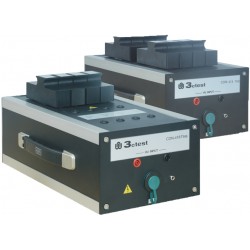
3ctest CDN 418TH8 CDN For Unshielded Symmetric High-Speed
-
Schwarzbeck CDN AF2 Coupling Decoupling Network
-
Schwarzbeck CDN AF3 Coupling Decoupling Network
-
Schwarzbeck CDN AF4 Coupling Decoupling Network
-
Schwarzbeck CDN AF6 Coupling Decoupling Network
-
Schwarzbeck CDN M4 32A Coupling Decoupling Network
-
Schwarzbeck CDNE M3 Coupling Decoupling Network
-
Schwarzbeck CDN AF8 Coupling Decoupling Network