
No products
Product successfully added to your shopping cart
There are 0 items in your cart. There is 1 item in your cart.
Conducted Susceptibility
- EMC Test Equipment
- Transient Generators
- RF Power Amplifiers
- DC - 300 kHz RF Amplifiers
- 10 kHz - 250 MHz RF Amplifiers
- 10 kHz - 400 MHz RF Amplifiers
- 10 kHz - 1 GHz RF Amplifiers
- 80 MHz - 1 GHz RF Amplifiers
- 1 GHz - 2 GHz RF Amplifiers
- 700 MHz - 4.2 GHz RF Amplifiers
- 1 GHz - 6 GHz RF Amplifiers
- 2 GHz - 8 GHz RF Amplifiers
- 6 GHz - 18 GHz RF Amplifiers
- 18 GHz - 40 GHz RF Amplifiers
- Pulse Amplifiers
- RF Field Strength Probes & Meters
- RF Conducted Immunity
- EMC Receivers/EMI Analyzers
- EMC Antennas
- Coupling Decoupling Networks (CDN's)
- Line Impedance Stabilization Networks (LISN's)
- RF Test Equipment
- EMC Probes
- EMC Measurement & Equipment Software
- Power Supplies
- Electrical Safety Analyzers
- High Precision Laboratory Power Analyzers & Meters
- Anechoic Chambers
- Over-the-Air (OTA) Test Chambers
- EMI RF Shielded Tent Enclosures
- RF Shielded Rooms
- EMC Absorber
- Positioning Equipment
- EMC/EMI Test Setup
- GTEM Cells / TEM Cells
- Reverberation Chambers
- Used RF Anechoic Chambers
- EMC Chamber Filters
- EMC Chamber Shielding Gaskets
- RF Shielded Doors
- Anechoic Chamber Accessories
- Fully Anechoic (FAR) Test Chambers
- Manufacturers
- 3ctest
- AE Techron
- AH Systems
- Amplifier Research
- Boonton
- Com-Power
- Diamond Engineering
- EM Test (Ametek CTS)
- EMC Partner
- EMC Test Design
- Empower High Power RF Amplifiers
- ETS-lindgren
- Log Periodic Dipole Array Antenna
- Near Field Probe Sets
- Double Ridge Horn Antennas
- Biconical Antennas
- Quad Ridge Horn Antennas
- Electric Field Probes
- GTEM's
- Positioners & Tripods
- Loop Antennas
- Biconilog Antennas
- LISN's (Line Impedance Stabilization Network)
- Shielded Enclosures/Rooms
- Monopole Antennas
- Field Generating Antennas
- Fischer Custom Communications
- Haefely Hipotronics
- Haefely EFT/Burst Immunity Test Systems
- Haefely Surge Combination Wave Test Systems
- Haefely Surge Damped Oscillating Wave Test Systems
- Haefely Electrostatic Discharge Test Systems (ESD)
- Haefely Surge Ring Wave Test Systems
- Haefely Surge Telecom Wave Test Systems
- Haefely Magnetic Field Test Systems
- Haefely CDN's (Coupling/Decoupling Networks)
- IFI Amplifiers
- Keysight (Agilent)
- MVG - Microwave Vision Group
- PMM / Narda
- Rohde & Schwarz RF Test Equipment
- Rohde & Schwarz Broadband RF Amplifiers
- Rohde & Schwarz Spectrum Analyzers
- Rohde & Schwarz Compliant EMI Test Receivers
- Rohde & Schwarz Isotropic RF Probes
- Rohde & Schwarz RF Signal Generators
- Rohde & Schwarz RF Switches
- Rohde & Schwarz Oscilloscopes
- Rohde & Schwarz RF Power Meters
- Rohde & Schwarz RF Power Sensors
- Schloder
- Schwarzbeck Mess-Elektronik
- Schwarzbeck Antennas
- Schwarzbeck Automotive Antennas
- Schwarzbeck Broadband Horn Antennas
- Schwarzbeck Biconical Antennas
- Schwarzbeck Logarithmic Periodic Broadband Antennas
- Schwarzbeck Stacked Log-Periodic Broadband Antennas
- Schwarzbeck Biconic Log-Periodic Antennas
- Schwarzbeck Dipole Antennas
- Schwarzbeck Rod Antennas
- Schwarbeck Antenna Baluns / Holders
- Schwarzbeck LISN Line Impedance Stabilisation Networks
- Schwarbeck Decoupling & Absorbing Clamps
- Schwarzbeck Field Probes
- Schwarzbeck Helmholtz Coils
- Schwarzbeck Antenna Masts
- Schwarzbeck Coupling/Decoupling Networks
- Schwarzbeck Antennas
- Solar Electronics
- Teseq (Schaffner)
- Teseq Automotive Transient Generators
- Teseq RF Test Equipment
- Teseq EFT/Burst Generators
- Teseq RF Immunity Generators
- Teseq ESD Guns
- Teseq Surge Generators
- Teseq Harmonics & Flicker Solutions
- Teseq Dips, Interrupts & Variations Equipment
- Teseq Ring Wave Generators
- Teseq Oscillatory Waves Generators
- Teseq Absorbing Clamps / Ferrite Tube
- Teseq EMC Antennas
- Teseq Current Probes
- Teseq Coupling Networks
- Thermo Keytek
- Vicreate
- Compliance Standards
- International (IEC/EN)
- EN/IEC 61000-3-2
- EN/IEC 61000-3-3
- IEC 61000-3-11
- IEC / EN 610000-3-12
- EN/IEC 61000-4-2
- EN/IEC 61000-4-3
- EN/IEC 61000-4-4
- EN/IEC 61000-4-5
- EN/IEC 61000-4-6
- EN/IEC 61000-4-7
- EN/IEC 61000-4-8
- EN/IEC 61000-4-9
- EN/IEC 61000-4-10
- EN/IEC 61000-4-11
- EN/IEC 61000-4-12
- EN/IEC 61000-4-16
- EN/IEC 61000-4-18
- EN/IEC 61000-4-19
- EN/IEC 61000-4-20
- EN/IEC 61000-4-21
- EN/IEC 61000-4-29
- EN/IEC 61000-4-31
- IEC 61000-4-39
- EN/IEC 62132
- SEMI F47 Voltage Sag Immunity
- Product Standards
- Military & Aerospace Standards
- Automotive EMC Standards
- CISPR Standards
- Telecom Testing
- ANSI/IEEE Standards
- FCC Part 15
- FCC Part 30
- International (IEC/EN)
- Application/Test Type
- Radiated Immunity
- Bulk Current Injection Testing
- RF Emissions Testing
- Conducted Immunity
- Conducted Emissions
- Antenna Pattern Measurement
- CE Mark Testing
- Intentional Radiator Testing
- Pulsed HIRF Radar
- Over-the-Air (OTA) Testing
- 5G Test Solutions
- Automotive EMC
- SAR Measurement Equipment
- Radiated Emissions
- Battery Simulator Test Equipment
- Services
- Clearance
Viewed products
-

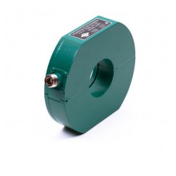
Schwarzbeck LFPA 9733...
5 Hz to 1 MHz Multi-Purpose Power...
-

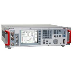
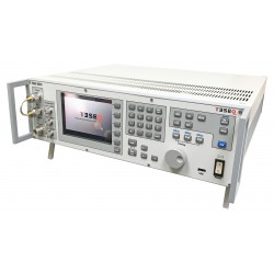
Rohde & Schwarz (R&S)...
Remote control via GPIB, Ethernet or...
 View larger

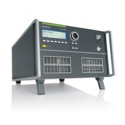
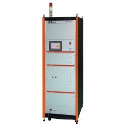
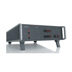
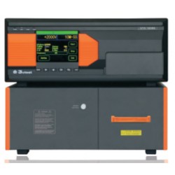
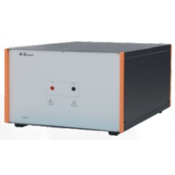
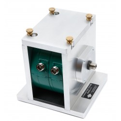
Schwarzbeck LFPA 9733 Power Amplifier 5Hz - 1MHz
New
- 5 Hz to 1 MHz
- Multi-Purpose Power Amplifier
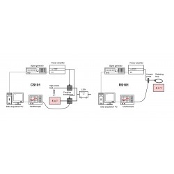
- Typical applications are magnetic immunity testing;
- According to automotive standards or MIL-461 E or F
- Frequency range (nominal): 5 Hz - 1 MHz
- Gain at 8 ohm impedance: 26 dB ±3 dB
PDF Downloads
Test Equipment Description
The Schwarzbeck LFPA 9733 is a multi-purpose power amplifier and can be used within the frequency range from 5 Hz to 1 MHz. Typical applications are magnetic immunity testing according to automotive standards and MIL-461E or F.
| Specifications | |
| Frequency range (nominal) | 5Hz – 1 MHz |
| Gain at 8 Ω impedance | 26 dB ±3 dB |
| AC Output current (50% duty cycle up to 5 min.) | 28 Arms |
| AC Continuous operating current | 14 Arms |
| AC Impedance of load min. | 1.0 Ω @ 5 Hz .. 15 Hz 0.25 Ω @ AC>15 Hz |
| Max. output voltage / current | 60 Vpeak @ 40 Apeak @ 5Hz .. 500 kHz 40 Vpeak @ 20 Apeak @ > 500 kHz |
| Typical input resistance | 10 kΩ |
| Input jack | BNC |
| Output Connectors | Flügelklemmen Wing terminals |
| Total harmonic distortion at 8 Ω impedance | <2% |
| Ambient temperature | -10°C/+40°C |
| Power supply | 230 VAC Power-Con (weitere auf Anfrage, others on request) |
| Current consumption | |
| Material of the housing | Aluminium |
| Housing dimensions (W x D x H) | 448 x 410 x 268 mm |
| Overall dimensions | 448 x 473 x 280 mm |
| Weight | 39 kg |
Hazard warning:
The power cord must be disconnected every time if wires are being connected or disconnected
Attention: During operation dangerous to life high voltages occur at the terminals of the LFPA 9733. If used in an inappropriate way this could lead to a life-threatening situation for the user.
Danger to life!
After the LFPA 9733 is connected to mains it is in standby mode. This is indicated by the orange LED. The CPU supervises the input voltage and the temperature of the amplifier even when in standby mode. To switch the unit on you have to push the “On” button. Along this way the internal modules are activated and checked. After this power on sequence the amplifier is ready for operation.
The display informs about the firmware version, the output voltage, the output current and also the temperature of the transformers/output stage. The signal input is muted when the amplifier has been switched on. This is indicated at the undermost line of the display.

The display informs about the actual peak values of the positive half-wave and the negative half-wave.
Voltage (Up):
Up: positive half-wave / negative half-wave
Current (Ip):
Ip: positive half-wave / negative half-wave
Temperature:
tA+: pos. output stage tA-: neg. output stage
tT1: transformer 1 tT2: transformer 2
By pushing the rotary-encoder (Level / Mute) the signal input can be enabled. You can adjust the output level (256 steps) by rotating the rotaryencoder. The output level is displayed at the undermost line as percentage quotation and stylized as bar chart.
The output voltage of the power amplifier LFPA 9733 is at the maximum when a level of approx. 2.5 Vrms (3.5 Vpeak) is applied to the input and the LEVEL control is set to “100%”. The use of an oscilloscope is recommended to monitor the output voltage.
The load impedance for frequencies lower than 15 Hz must be at least 1.0 Ω. The maximum current must not exceed 20 Arms.
The amplifier is fused with a slow blow 12.5 A fuse at the primary side.
The signal can be tapped from the red wing terminal. The blue wing terminal “COMMON” is connected to the housing electrically.
Even when the amplifier is in standby mode the fans operate at high temperatures.
Please note that the air intake for cooling purposes is located at the side and at the bottom of the amplifier and the warm air is exhausted at the back. The amplifier must not be installed closer than 10 cm to a wall. It has to be installed in a way that the exhausted warm air cannot get into the housing again (thermal short). Pay attention to cooling especially when installing the amp into a 19” rack!
A 19’’-rack mount kit is available optionally.
Interfaces
The amplifier has three external interfaces to communicate with a PC. USB, RS232 and GPIB.
Configuration
You can enter the configuration menu of the interfaces by pushing the rotary-encoder while in standby mode. From here you can chose from three options:
GPIB interface
USB interface
Serial interface
By rotating the rotary encoder the interface can be chosen and will be shown inverse.

Pushing the rotary encoder shows further options of the serial/GPIB interface.
The baud rate of the serial interface can be chosen. The following parameters cannot be changed: 8 data bits, no parity, one stop bit.
The address of the GPIB interface can be set from 1 to 31.
The chosen parameter gets selected by pushing the rotary encoder. The changes will be saved and the amplifier returns into standby mode.
Associated EMC Test Equipment
30 other products in the same category:
-
EM Test CWS 500N2 RF Conducted Immunity/BCI for Automotive & Mil-Std 461 CS 114
-

Pearson 8705C Current Probe for MIL-STD-461 CS114, CS115, CS116
-
Pearson Model F-3 Calibration Fixture for MIL-STD-461 CS114, CS115, CS116
-
Solar Type 9124-1N Clamp On Current Probe, 1 kHz - 200 MHz
-
Montena Turn Key Solution for MIL-STD-461 CS101 and RS101 EMC Compliance
-
Em Test CWS 500N3 Test Generator for Mil-STD-461, ISO 11452 and More
-
3ctest LSS 160MS Multiple Stroke Lightning Transient Generator for DO-160 & MIL-STD-461G CS 117
-
Rent Teseq NSG 4070C-45 Test System for Conducted & Radiated Immunity
-
Montena Turn Key Solution for MIL-STD-461 CS114, CS115, CS116 EMC Compliance
-
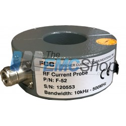
Rent Fischer F-52 Current Monitor Probe 10kHz – 500MHz
-
EM Test CN 200N1 Audio Transformer Assembly for LF Conducted Immunity Testing
-
Solar 9354-1 Transient Generator for MIL-STD-461 CS116
-
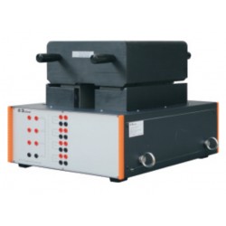
3ctest ETS 160MB Multiple Burst Test System Waveform W2, W3, W6 for DO-160 Section 22
-
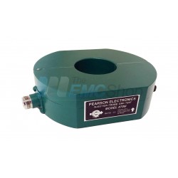
Pearson 8700i Bulk Current Injection Probe for MIL-STD-461 CS114, CS115, CS116
-

3ctest ETS 160MB Waveform Module for DO-160 Section 22 Testing
-

3ctest LSU-1 Low Level Waveform Attenuation Module for LSS160SS Lightning Generator
-
3ctest MD-W5B Module for LSS160 Series Lightning Test System
-
3ctest LCT-1 Current Coupling Transformer for LSS Series Lightning Testers, W1, W5A, W5B Current Wave Coupling up to 10 kA
-
3ctest LVT-1 Voltage Coupling Transformer for LSS Series Lightning Testers, W4, W5A, W5B Voltage Wave Coupling up to 1.6 kV
-
3ctest LVT-2 High Frequency Voltage Coupling Transformer for ETS160MB up to 4 kV
-
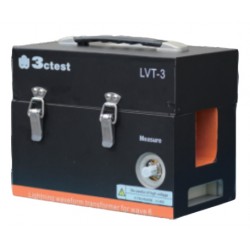
3ctest LVT-3 High Frequency Current Coupling Transformer for ETS160MB up to 160 Amps
-
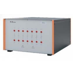
3ctest CN-1 Mains Supply Coupling Unit for W4, W5A, W5B Surge Wave Coupling up to 420 Volts
-

3ctest DN 416T Mains Supply Decoupling Unit for Pin Injection W4, W5A, W5B Waveforms
-
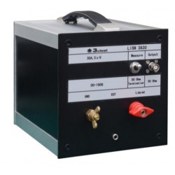
3ctest LISN 3830 Linear Impedance Stability Network for RTCA/DO-160G up to 400V, 30A
-
3ctest LISN 45200 Linear Impedance Stability Network for RTCA DO-160 Section 22 up to 450V, 200A
-
3ctest C28000 Capacitor for LISN Cable Bundle DO-160 Section 22 Testing up to 400V, 28000 uF
-
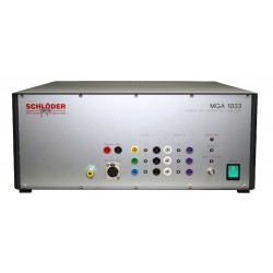
Schloder MGA 1030 DC - 250 kHz Magnetic Field System
-
Teseq NSG 4070C-80 Integrated Signal Generator, 4 kHz to 1 GHz, 80 W Integrated Class A Power Amplifier
-
Pearson MIL-STD-461 and DO-160 Current Probe Set
-
Rent Pearson 8705C Current Probe for MIL-STD-461 CS114, CS115, CS116