
No products
Product successfully added to your shopping cart
There are 0 items in your cart. There is 1 item in your cart.
Radiated Immunity
- EMC Test Equipment
- Transient Generators
- RF Power Amplifiers
- DC - 300 kHz RF Amplifiers
- 10 kHz - 250 MHz RF Amplifiers
- 10 kHz - 400 MHz RF Amplifiers
- 10 kHz - 1 GHz RF Amplifiers
- 80 MHz - 1 GHz RF Amplifiers
- 1 GHz - 2 GHz RF Amplifiers
- 700 MHz - 4.2 GHz RF Amplifiers
- 1 GHz - 6 GHz RF Amplifiers
- 2 GHz - 8 GHz RF Amplifiers
- 6 GHz - 18 GHz RF Amplifiers
- 18 GHz - 40 GHz RF Amplifiers
- Pulse Amplifiers
- RF Field Strength Probes & Meters
- RF Conducted Immunity
- EMC Receivers/EMI Analyzers
- EMC Antennas
- Coupling Decoupling Networks (CDN's)
- Line Impedance Stabilization Networks (LISN's)
- RF Test Equipment
- EMC Probes
- EMC Measurement & Equipment Software
- Power Supplies
- Electrical Safety Analyzers
- High Precision Laboratory Power Analyzers & Meters
- Anechoic Chambers
- Over-the-Air (OTA) Test Chambers
- EMI RF Shielded Tent Enclosures
- RF Shielded Rooms
- EMC Absorber
- Positioning Equipment
- EMC/EMI Test Setup
- GTEM Cells / TEM Cells
- Reverberation Chambers
- Used RF Anechoic Chambers
- EMC Chamber Filters
- EMC Chamber Shielding Gaskets
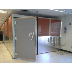
- RF Shielded Doors
- Anechoic Chamber Accessories
- Fully Anechoic (FAR) Test Chambers
- Manufacturers
- 3ctest
- AE Techron
- AH Systems
- Amplifier Research
- Boonton
- Com-Power
- Diamond Engineering
- EM Test (Ametek CTS)
- EMC Partner
- EMC Test Design
- Empower High Power RF Amplifiers
- ETS-lindgren
- Log Periodic Dipole Array Antenna
- Near Field Probe Sets
- Double Ridge Horn Antennas
- Biconical Antennas
- Quad Ridge Horn Antennas
- Electric Field Probes
- GTEM's
- Positioners & Tripods
- Loop Antennas
- Biconilog Antennas
- LISN's (Line Impedance Stabilization Network)
- Shielded Enclosures/Rooms
- Monopole Antennas
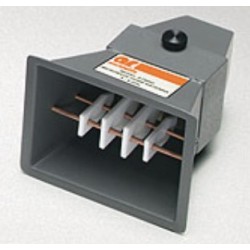
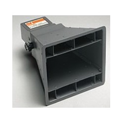
- Field Generating Antennas
- Fischer Custom Communications
- Haefely Hipotronics
- Haefely EFT/Burst Immunity Test Systems
- Haefely Surge Combination Wave Test Systems
- Haefely Surge Damped Oscillating Wave Test Systems
- Haefely Electrostatic Discharge Test Systems (ESD)
- Haefely Surge Ring Wave Test Systems
- Haefely Surge Telecom Wave Test Systems
- Haefely Magnetic Field Test Systems
- Haefely CDN's (Coupling/Decoupling Networks)
- IFI Amplifiers
- Keysight (Agilent)
- MVG - Microwave Vision Group
- PMM / Narda
- Rohde & Schwarz RF Test Equipment
- Rohde & Schwarz Broadband RF Amplifiers
- Rohde & Schwarz Spectrum Analyzers
- Rohde & Schwarz Compliant EMI Test Receivers
- Rohde & Schwarz Isotropic RF Probes
- Rohde & Schwarz RF Signal Generators
- Rohde & Schwarz RF Switches
- Rohde & Schwarz Oscilloscopes
- Rohde & Schwarz RF Power Meters
- Rohde & Schwarz RF Power Sensors
- Schloder
- Schwarzbeck Mess-Elektronik
- Schwarzbeck Antennas
- Schwarzbeck Automotive Antennas
- Schwarzbeck Broadband Horn Antennas
- Schwarzbeck Biconical Antennas
- Schwarzbeck Logarithmic Periodic Broadband Antennas
- Schwarzbeck Stacked Log-Periodic Broadband Antennas
- Schwarzbeck Biconic Log-Periodic Antennas
- Schwarzbeck Dipole Antennas
- Schwarzbeck Rod Antennas
- Schwarbeck Antenna Baluns / Holders
- Schwarzbeck LISN Line Impedance Stabilisation Networks
- Schwarbeck Decoupling & Absorbing Clamps
- Schwarzbeck Field Probes
- Schwarzbeck Helmholtz Coils
- Schwarzbeck Antenna Masts
- Schwarzbeck Coupling/Decoupling Networks
- Schwarzbeck Antennas
- Solar Electronics
- Teseq (Schaffner)
- Teseq Automotive Transient Generators
- Teseq RF Test Equipment
- Teseq EFT/Burst Generators
- Teseq RF Immunity Generators
- Teseq ESD Guns
- Teseq Surge Generators
- Teseq Harmonics & Flicker Solutions
- Teseq Dips, Interrupts & Variations Equipment
- Teseq Ring Wave Generators
- Teseq Oscillatory Waves Generators
- Teseq Absorbing Clamps / Ferrite Tube
- Teseq EMC Antennas
- Teseq Current Probes
- Teseq Coupling Networks
- Thermo Keytek
- Vicreate
- Compliance Standards
- International (IEC/EN)
- EN/IEC 61000-3-2
- EN/IEC 61000-3-3
- IEC 61000-3-11
- IEC / EN 610000-3-12
- EN/IEC 61000-4-2
- EN/IEC 61000-4-3
- EN/IEC 61000-4-4
- EN/IEC 61000-4-5
- EN/IEC 61000-4-6
- EN/IEC 61000-4-7
- EN/IEC 61000-4-8
- EN/IEC 61000-4-9
- EN/IEC 61000-4-10
- EN/IEC 61000-4-11
- EN/IEC 61000-4-12
- EN/IEC 61000-4-16
- EN/IEC 61000-4-18
- EN/IEC 61000-4-19
- EN/IEC 61000-4-20
- EN/IEC 61000-4-21
- EN/IEC 61000-4-29
- EN/IEC 61000-4-31
- IEC 61000-4-39
- EN/IEC 62132
- SEMI F47 Voltage Sag Immunity
- Product Standards
- Military & Aerospace Standards
- Automotive EMC Standards
- CISPR Standards
- Telecom Testing
- ANSI/IEEE Standards
- FCC Part 15
- FCC Part 30
- International (IEC/EN)
- Application/Test Type
- Radiated Immunity
- Bulk Current Injection Testing
- RF Emissions Testing
- Conducted Immunity
- Conducted Emissions
- Antenna Pattern Measurement
- CE Mark Testing
- Intentional Radiator Testing
- Pulsed HIRF Radar
- Over-the-Air (OTA) Testing
- 5G Test Solutions
- Automotive EMC
- SAR Measurement Equipment
- Radiated Emissions
- Battery Simulator Test Equipment
- Services
- Clearance
Viewed products
-

Teseq SL 90 Strip Line...
EMC tests for vehicle components...
-

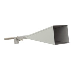
QRHA40G 18 GHz to 40...
Suitable for used between 18 GHz and...


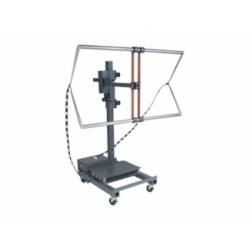
Teseq SL 90 Strip Line 90 Ω DC to 1000 MHz
New
- EMC tests for vehicle components
- Immunity to RF fields
- Conformity with the requirements of ISO 11452-5
- Efficient power conversion provides high field with minimum power
Specifications
| Standards Met | ISO 11452-5 CISPR 25 IEC/EN 61000-4-20 |
| Stripline Conform with ISO 11452-5 | |
| Parameter | Value |
| Frequency range | DC to 1000 MHz |
| Max. input power | 150 W |
| Connector type | N (female), 50 Ω |
| Typical impedance | 90 Ω |
| Net power for 10 V/m as calculated according ISO 11452-5 | approx. 50 mW (17 dBm) |
| Distance between the plates | Height of the septum: 150 mm |
| General Data Technical Details | |
| Parameter | Value |
| Dimensions | 3.5 x 0.9 x 1.17 |
| Weight | approx. 80 kg |
Test Equipment Description
Teseq SL 90 Strip Line Description:
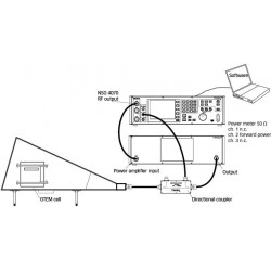
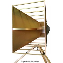
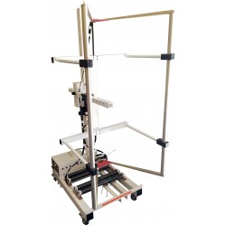
The transversal electromagnetic mode which can developed in the SL 90 strip line, provides the opportunity for doing EMC testing inside the strip line. The geometrical dimensions having a line impedance of Z = 90 Ω. At the end, the line is matched by a 90 Ω termination. Typical for this strip line is the low power request for high field strength values. The strip line is specified in ISO 11452-5 ‘Road Vehicles electrical disturbances through radiated narrowband electromagnetic energy: Measurement procedure for components part 5: Strip Line’. The SL 90 allows testing electrical/electronic sub modules (EUB) and their associated cables. Standards like BMW GS 95002 allow both emission and immunity testing with the strip line. Although emission testing is derived from ISO 11452-5 where the strip line is exclusively used for immunity tests. BMW GS 95002 provides additional hints. The limit line is given as interference voltage level in dμBV.
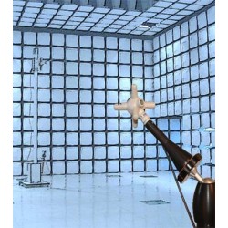
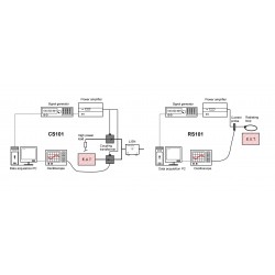
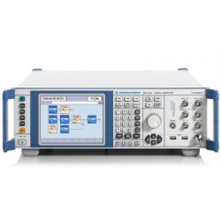
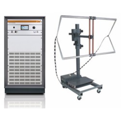
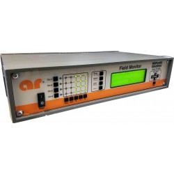
The SL 90 consists of two parallel metal plates. The EUT is arranged in the middle between these plates. The largest outer dimension of the EUT should not be more than 1/3 of the plate distance. The ground is on the lower plate and the isolated upper plate is supplied with RF energy. Between the plates, an electromagnetic field will be established. A typical test configuration consists of signal generator, power amplifiers, power meters and SL 90. To avoid interactions with the environment, the test should be run in an anechoic test chamber.
Applicable Standards:
28 other products in the same category:
-
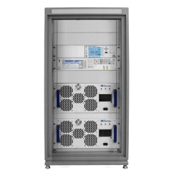
Radiated Immunity Test System
-
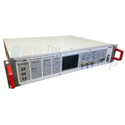
Teseq ITS 6006 Radiated Immunity Test System for IEC 61000-4-3
-
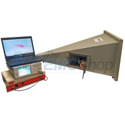
Radiated Immunity Test System for IEC 61000-4-20 TEM Waveguides
-
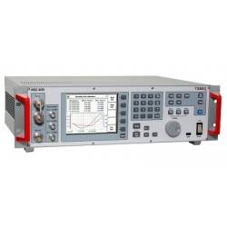
Teseq NSG 4070B Conducted & Radiated Immunity Test System
-
Turn-Key Radiated Immunity Test System for IEC 61000-4-3 Level 1, 3 V/m
-
AH Systems SAS-570 Double Ridge Horn Antenna, 170 MHz - 3 GHz
-
Amplifier Research (AR) ATR80M6G Wide Band, High Gain Log Periodic Antenna
-
Monthly Rental - ETS Lindgren 3164-05 Open Boundary Quad-Ridged Horn 2 - 18 GHz
-
Universal Shielding Corp 14kHz - 10 GHz RFI/EMI Shielding Enclosure 12' x 20' x 8'
-

Com-Power PC-114 EMC Pre-Compliance Emissions Test System 9 KHz - 1 GHz
-
Narda PMM Rad-IS RF Radiated Immunity System for IEC/EN 61000-4-3
-
Amplifier Research ATH7G18 2800 Watt Horn Antenna 7.5 - 18 GHz
-
Amplifier Research ATH4G8 500 Watt Horn Antenna 4 - 8 GHz
-
Montena Turn Key Solution for MIL-STD-461 CS101 and RS101 EMC Compliance
-
Teseq ITS 6006B Radiated Immunity Test System 80 MHz to 6 GHz
-

Rent 30 V/m Turn-Key Radiated Immunity Test System per IEC 61000-4-3
-
Amplifier Research AT 5000 E-Field Generator for Precompliance RFI Testing
-
Keysight (Agilent/HP) E8247C-520 PSG Signal Generator, 250 kHz to 20 GHz
-
Rohde & Schwarz (R&S) SMF100A Signal Generator 100kHz to 22GHz
-
TDK EFG-03 High Power E-Field Generator 10 kHz - 100 MHz, up to 500 V/m
-
Mil-STD-461 RS103 2 MHz - 100 MHz Field Generation Test Equipment Package
-
Amplifier Research FM5004 E and H Field Monitor
-
Rent TDK EFG-03 High Power E-Field Generator 10 kHz - 100 MHz, up to 500 V/m
-
Amplifier Research FA7040/Kit Electric Field Analyzer
-
EMC Pioneer Anechoic Chamber Project
-
HA26G 18 - 26.5 GHz Pyramidal Horn Antenna, 26 dBi Gain
-
Agilent HP Keysight E8241A Performance Signal Generator PSG-L Series
-
SGHA8G Standard Gain Horn Antenna, 4 - 8 GHz