No products
Product successfully added to your shopping cart
There are 0 items in your cart. There is 1 item in your cart.
Schwarzbeck Automotive Antennas
- EMC Test Equipment
- Transient Generators
- RF Power Amplifiers
- DC - 300 kHz RF Amplifiers
- 10 kHz - 250 MHz RF Amplifiers
- 10 kHz - 400 MHz RF Amplifiers
- 10 kHz - 1 GHz RF Amplifiers
- 80 MHz - 1 GHz RF Amplifiers
- 1 GHz - 2 GHz RF Amplifiers
- 700 MHz - 4.2 GHz RF Amplifiers
- 1 GHz - 6 GHz RF Amplifiers
- 2 GHz - 8 GHz RF Amplifiers
- 6 GHz - 18 GHz RF Amplifiers
- 18 GHz - 40 GHz RF Amplifiers
- Pulse Amplifiers
- RF Field Strength Probes & Meters
- RF Conducted Immunity
- EMC Receivers/EMI Analyzers
- EMC Antennas
- Coupling Decoupling Networks (CDN's)
- Line Impedance Stabilization Networks (LISN's)
- RF Test Equipment
- EMC Probes
- EMC Measurement & Equipment Software
- Power Supplies
- Electrical Safety Analyzers
- High Precision Laboratory Power Analyzers & Meters
- Anechoic Chambers
- Over-the-Air (OTA) Test Chambers
- EMI RF Shielded Tent Enclosures
- RF Shielded Rooms
- EMC Absorber
- Positioning Equipment
- EMC/EMI Test Setup
- GTEM Cells / TEM Cells
- Reverberation Chambers
- Used RF Anechoic Chambers
- EMC Chamber Filters
- EMC Chamber Shielding Gaskets
- RF Shielded Doors
- Anechoic Chamber Accessories
- Fully Anechoic (FAR) Test Chambers
- Manufacturers
- 3ctest
- AE Techron
- AH Systems
- Amplifier Research
- Boonton
- Com-Power
- Diamond Engineering
- EM Test (Ametek CTS)
- EMC Partner
- EMC Test Design
- Empower High Power RF Amplifiers
- ETS-lindgren
- Log Periodic Dipole Array Antenna
- Near Field Probe Sets
- Double Ridge Horn Antennas
- Biconical Antennas
- Quad Ridge Horn Antennas
- Electric Field Probes
- GTEM's
- Positioners & Tripods
- Loop Antennas
- Biconilog Antennas
- LISN's (Line Impedance Stabilization Network)
- Shielded Enclosures/Rooms
- Monopole Antennas
- Field Generating Antennas
- Fischer Custom Communications
- Haefely Hipotronics
- Haefely EFT/Burst Immunity Test Systems
- Haefely Surge Combination Wave Test Systems
- Haefely Surge Damped Oscillating Wave Test Systems
- Haefely Electrostatic Discharge Test Systems (ESD)
- Haefely Surge Ring Wave Test Systems
- Haefely Surge Telecom Wave Test Systems
- Haefely Magnetic Field Test Systems
- Haefely CDN's (Coupling/Decoupling Networks)
- IFI Amplifiers
- Keysight (Agilent)
- MVG - Microwave Vision Group
- PMM / Narda
- Rohde & Schwarz RF Test Equipment
- Rohde & Schwarz Broadband RF Amplifiers
- Rohde & Schwarz Spectrum Analyzers
- Rohde & Schwarz Compliant EMI Test Receivers
- Rohde & Schwarz Isotropic RF Probes
- Rohde & Schwarz RF Signal Generators
- Rohde & Schwarz RF Switches
- Rohde & Schwarz Oscilloscopes
- Rohde & Schwarz RF Power Meters
- Rohde & Schwarz RF Power Sensors
- Schloder
- Schwarzbeck Mess-Elektronik
- Schwarzbeck Antennas
- Schwarzbeck Automotive Antennas
- Schwarzbeck Broadband Horn Antennas
- Schwarzbeck Biconical Antennas
- Schwarzbeck Logarithmic Periodic Broadband Antennas
- Schwarzbeck Stacked Log-Periodic Broadband Antennas
- Schwarzbeck Biconic Log-Periodic Antennas
- Schwarzbeck Dipole Antennas
- Schwarzbeck Rod Antennas
- Schwarbeck Antenna Baluns / Holders
- Schwarzbeck LISN Line Impedance Stabilisation Networks
- Schwarbeck Decoupling & Absorbing Clamps
- Schwarzbeck Field Probes
- Schwarzbeck Helmholtz Coils
- Schwarzbeck Antenna Masts
- Schwarzbeck Coupling/Decoupling Networks
- Schwarzbeck Antennas
- Solar Electronics
- Teseq (Schaffner)
- Teseq Automotive Transient Generators
- Teseq RF Test Equipment
- Teseq EFT/Burst Generators
- Teseq RF Immunity Generators
- Teseq ESD Guns
- Teseq Surge Generators
- Teseq Harmonics & Flicker Solutions
- Teseq Dips, Interrupts & Variations Equipment
- Teseq Ring Wave Generators
- Teseq Oscillatory Waves Generators
- Teseq Absorbing Clamps / Ferrite Tube
- Teseq EMC Antennas
- Teseq Current Probes
- Teseq Coupling Networks
- Thermo Keytek
- Vicreate
- Compliance Standards
- International (IEC/EN)
- EN/IEC 61000-3-2
- EN/IEC 61000-3-3
- IEC 61000-3-11
- IEC / EN 610000-3-12
- EN/IEC 61000-4-2
- EN/IEC 61000-4-3
- EN/IEC 61000-4-4
- EN/IEC 61000-4-5
- EN/IEC 61000-4-6
- EN/IEC 61000-4-7
- EN/IEC 61000-4-8
- EN/IEC 61000-4-9
- EN/IEC 61000-4-10
- EN/IEC 61000-4-11
- EN/IEC 61000-4-12
- EN/IEC 61000-4-16
- EN/IEC 61000-4-18
- EN/IEC 61000-4-19
- EN/IEC 61000-4-20
- EN/IEC 61000-4-21
- EN/IEC 61000-4-29
- EN/IEC 61000-4-31
- IEC 61000-4-39
- EN/IEC 62132
- SEMI F47 Voltage Sag Immunity
- Product Standards
- Military & Aerospace Standards
- Automotive EMC Standards
- CISPR Standards
- Telecom Testing
- ANSI/IEEE Standards
- FCC Part 15
- FCC Part 30
- International (IEC/EN)
- Application/Test Type
- Radiated Immunity
- Bulk Current Injection Testing
- RF Emissions Testing
- Conducted Immunity
- Conducted Emissions
- Antenna Pattern Measurement
- CE Mark Testing
- Intentional Radiator Testing
- Pulsed HIRF Radar
- Over-the-Air (OTA) Testing
- 5G Test Solutions
- Automotive EMC
- SAR Measurement Equipment
- Radiated Emissions
- Battery Simulator Test Equipment
- Services
- Clearance
Viewed products
-

Schwarzbeck 420 NJ...
Elements for radiated immunity caused...
Schwarzbeck 420 NJ Elements For SBA 9113 Balun
New
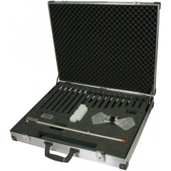
- Elements for radiated immunity caused by hand portable transmitters
- with SBA 9113 or SBA 9113 mini version for the Ford standard RI115 (Ford EMC CS 2009)
Option:
- Opt: Spacer 50
- Spacer made of Polystyrene to set the 420 NJ elements test distance to 50 mm.
PDF Downloads
Test Equipment Description
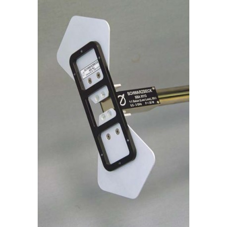
The 420NJ elements for the SBA 9113 were designed because of the drastical increase of mobile phones and handheld transmitters within the last years. Various disturbances generated a need for new, more efficient immunity test methods with good reproducability. Existing radiated immunity tests with test distances typically between 1 m to 3 m require expensive power amplifiers. Several investigations in the very close surrounding of mobile phones and handheld transmitters have shown, that such devices can generate very high fieldstrengths in the order of some 100 V/m with only a few Watt power. With existing immunity test methods the effort is extremely high to generate fieldstrength level as described before.
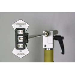
Thanks to the special shape of the 420NJ elements both can be achieved simultaneously, an enormous bandwidth and a very close distance to the EuT surface, typically 5 mm. This is an economic way to generate very high fieldstrengths with moderate power of e.g. 10 to 20 Watt. The large bandwidth of the radiating elements allows fast wideband testing without any need for antenna changes, therefore even country specific frequency bands can be tested without extra effort.
Application
The typical application of the SBA 9113 with 420NJ-elements is immunity testing of components in the automotive industry, medical, scientific or aerospace environment, where immunity against handheld transmitters is an important topic. Usually the surface of an EuT is divided into a grid with a meshwidth of e.g. 10 cm. Each gridpoint is tested for two orthogonal polarisations with the desired fieldstrength while observing the EuT condition. Typical Antenna to EuT spacings are 5 mm or 50 mm, which are provided by respective spacers of the antenna elements.
The 420NJ-elements are mounted with M4 screws at the element fixture nuts of the Balun. When mounting the flat elements care should be taken in order to avoid overtightening the threads. It is absolutely sufficient to tighten the element screws with moderate torque. Various experiments have shown that the contact at the feedpoint is always sufficient.

| Key | Description |
| 1 | SBA 9113 broadband low loss balun |
| 2 | 420NJ flat antenna elements |
| 3 | N-female connector |
| 4 | Element fixture and spacing frame (5 mm, non metallic) |
| 5 | Symmetrical terminals M4 |
| 6 | 22 mm tube for handling and fixture |

420NJ Elements for SBA 9113 Balun
The functional check of the SBA 9113 can be made measuring the VSWR at the N-connector of the antenna rod. The radiating antenna elements must be connected to the balun.
The VSWR depends on environmental reflections, therefore a minimum spacing of 30 cm to any reflective obstacle should be maintained. The voltage standing wave ratio is defined as the sum of the forward and reflected voltage divided through the difference of forward and reflected voltage. The VSWR can also be expressed as reflection coefficient or return loss (RL, |S11|). The reflection coefficient r is the ratio of reflected and forward voltage. The following tabular provides correspondences for the most common values, missing values can be calculated by the given equations.
| Specifications | |
| Flat, broadband antenna elements for the SBA 9113 Balun (also compatible with SBA 9113B and SBA 9113 Short Version) for efficient immunity testing at close distances. Linear Polarisation. | |
| Frequency range | 360 MHz - 2.7 GHz |
| Element length total | LE =240 mm |
| Element width | D = 109 mm |
| Element fixture | M 4 x 8 |
| Spacer | 5 mm 50 mm |
| SWR typ. | 1-4 |
| Balun (low loss) | 1:1 |
| Max. Input Power | 20 W |
| Weight | 135 g |

