
No products
Product successfully added to your shopping cart
There are 0 items in your cart. There is 1 item in your cart.
Schwarzbeck Automotive Antennas
- EMC Test Equipment
- Transient Generators
- RF Power Amplifiers
- DC - 300 kHz RF Amplifiers
- 10 kHz - 250 MHz RF Amplifiers
- 10 kHz - 400 MHz RF Amplifiers
- 10 kHz - 1 GHz RF Amplifiers
- 80 MHz - 1 GHz RF Amplifiers
- 1 GHz - 2 GHz RF Amplifiers
- 700 MHz - 4.2 GHz RF Amplifiers
- 1 GHz - 6 GHz RF Amplifiers
- 2 GHz - 8 GHz RF Amplifiers
- 6 GHz - 18 GHz RF Amplifiers
- 18 GHz - 40 GHz RF Amplifiers
- Pulse Amplifiers
- RF Field Strength Probes & Meters
- RF Conducted Immunity
- EMC Receivers/EMI Analyzers
- EMC Antennas
- Coupling Decoupling Networks (CDN's)
- Line Impedance Stabilization Networks (LISN's)
- RF Test Equipment
- EMC Probes
- EMC Measurement & Equipment Software
- Power Supplies
- Electrical Safety Analyzers
- High Precision Laboratory Power Analyzers & Meters
- Anechoic Chambers
- Over-the-Air (OTA) Test Chambers
- EMI RF Shielded Tent Enclosures
- RF Shielded Rooms
- EMC Absorber
- Positioning Equipment
- EMC/EMI Test Setup
- GTEM Cells / TEM Cells
- Reverberation Chambers
- Used RF Anechoic Chambers
- EMC Chamber Filters
- EMC Chamber Shielding Gaskets
- RF Shielded Doors
- Anechoic Chamber Accessories
- Fully Anechoic (FAR) Test Chambers
- Manufacturers
- 3ctest
- AE Techron
- AH Systems
- Amplifier Research
- Boonton
- Com-Power
- Diamond Engineering
- EM Test (Ametek CTS)
- EMC Partner
- EMC Test Design
- Empower High Power RF Amplifiers
- ETS-lindgren
- Log Periodic Dipole Array Antenna
- Near Field Probe Sets
- Double Ridge Horn Antennas
- Biconical Antennas
- Quad Ridge Horn Antennas
- Electric Field Probes
- GTEM's
- Positioners & Tripods
- Loop Antennas
- Biconilog Antennas
- LISN's (Line Impedance Stabilization Network)
- Shielded Enclosures/Rooms
- Monopole Antennas
- Field Generating Antennas
- Fischer Custom Communications
- Haefely Hipotronics
- Haefely EFT/Burst Immunity Test Systems
- Haefely Surge Combination Wave Test Systems
- Haefely Surge Damped Oscillating Wave Test Systems
- Haefely Electrostatic Discharge Test Systems (ESD)
- Haefely Surge Ring Wave Test Systems
- Haefely Surge Telecom Wave Test Systems
- Haefely Magnetic Field Test Systems
- Haefely CDN's (Coupling/Decoupling Networks)
- IFI Amplifiers
- Keysight (Agilent)
- MVG - Microwave Vision Group
- PMM / Narda
- Rohde & Schwarz RF Test Equipment
- Rohde & Schwarz Broadband RF Amplifiers
- Rohde & Schwarz Spectrum Analyzers
- Rohde & Schwarz Compliant EMI Test Receivers
- Rohde & Schwarz Isotropic RF Probes
- Rohde & Schwarz RF Signal Generators
- Rohde & Schwarz RF Switches
- Rohde & Schwarz Oscilloscopes
- Rohde & Schwarz RF Power Meters
- Rohde & Schwarz RF Power Sensors
- Schloder
- Schwarzbeck Mess-Elektronik
- Schwarzbeck Antennas
- Schwarzbeck Automotive Antennas
- Schwarzbeck Broadband Horn Antennas
- Schwarzbeck Biconical Antennas
- Schwarzbeck Logarithmic Periodic Broadband Antennas
- Schwarzbeck Stacked Log-Periodic Broadband Antennas
- Schwarzbeck Biconic Log-Periodic Antennas
- Schwarzbeck Dipole Antennas
- Schwarzbeck Rod Antennas
- Schwarbeck Antenna Baluns / Holders
- Schwarzbeck LISN Line Impedance Stabilisation Networks
- Schwarbeck Decoupling & Absorbing Clamps
- Schwarzbeck Field Probes
- Schwarzbeck Helmholtz Coils
- Schwarzbeck Antenna Masts
- Schwarzbeck Coupling/Decoupling Networks
- Schwarzbeck Antennas
- Solar Electronics
- Teseq (Schaffner)
- Teseq Automotive Transient Generators
- Teseq RF Test Equipment
- Teseq EFT/Burst Generators
- Teseq RF Immunity Generators
- Teseq ESD Guns
- Teseq Surge Generators
- Teseq Harmonics & Flicker Solutions
- Teseq Dips, Interrupts & Variations Equipment
- Teseq Ring Wave Generators
- Teseq Oscillatory Waves Generators
- Teseq Absorbing Clamps / Ferrite Tube
- Teseq EMC Antennas
- Teseq Current Probes
- Teseq Coupling Networks
- Thermo Keytek
- Vicreate
- Compliance Standards
- International (IEC/EN)
- EN/IEC 61000-3-2
- EN/IEC 61000-3-3
- IEC 61000-3-11
- IEC / EN 610000-3-12
- EN/IEC 61000-4-2
- EN/IEC 61000-4-3
- EN/IEC 61000-4-4
- EN/IEC 61000-4-5
- EN/IEC 61000-4-6
- EN/IEC 61000-4-7
- EN/IEC 61000-4-8
- EN/IEC 61000-4-9
- EN/IEC 61000-4-10
- EN/IEC 61000-4-11
- EN/IEC 61000-4-12
- EN/IEC 61000-4-16
- EN/IEC 61000-4-18
- EN/IEC 61000-4-19
- EN/IEC 61000-4-20
- EN/IEC 61000-4-21
- EN/IEC 61000-4-29
- EN/IEC 61000-4-31
- IEC 61000-4-39
- EN/IEC 62132
- SEMI F47 Voltage Sag Immunity
- Product Standards
- Military & Aerospace Standards
- Automotive EMC Standards
- CISPR Standards
- Telecom Testing
- ANSI/IEEE Standards
- FCC Part 15
- FCC Part 30
- International (IEC/EN)
- Application/Test Type
- Radiated Immunity
- Bulk Current Injection Testing
- RF Emissions Testing
- Conducted Immunity
- Conducted Emissions
- Antenna Pattern Measurement
- CE Mark Testing
- Intentional Radiator Testing
- Pulsed HIRF Radar
- Over-the-Air (OTA) Testing
- 5G Test Solutions
- Automotive EMC
- SAR Measurement Equipment
- Radiated Emissions
- Battery Simulator Test Equipment
- Services
- Clearance
Viewed products
-

Schwarzbeck HLC 27...
26.96 ... 27.4 MHz Frequency Range...
 View larger
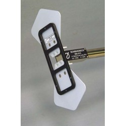
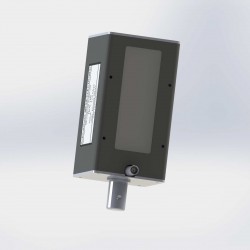
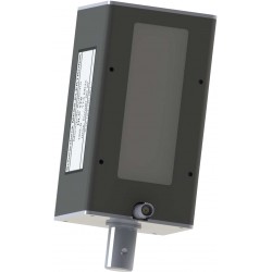
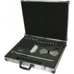
Schwarzbeck HLC 27 Dipole Antenna
New
- 26.96 ... 27.4 MHz Frequency Range
- Compact Dipole Antenna
- For automotive immunity testing, embedded in a plastic housing
- Original proposal of ISO 11452-9 had significant drawbacks;
- Made a practical realisation impossible
- High losses and high sheath currents were the main disadvantages of the original design
PDF Downloads
Test Equipment Description
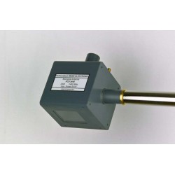
The HLC 27 is a Compact Dipole Antenna for automotive immunity testing, embedded in a plastic housing. The original proposal of ISO 11452-9 had significant drawbacks, which made a practical realisation impossible. Especially the small effective antenna area, high losses and high sheath currents were the main disadvantages of the original design. A shortened dipol with balun, fitting into the original housing was choosen to eliminate the previous mentioned drawbacks.
In order to maintain a high degree of symmetry, the coaxial antenna connector leaves the antenna at the center of the rear mounting bolt. This prevents the generation of unwanted sheath currents very effectively. A further reduction of sheath currents can be achieved using the optional coaxial cable loaded with clamp-on ferrites.
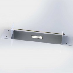
The antenna housing comes with two fixture bolts, which can be used to mount the antenna either in vertical or horizontal orientation.
CAUTION
The BNC antenna connector must not be touched during TX-operation due to hazardous voltages and fieldstrength! The relevant safety standards for exposition to electromagnetic fields must be considered. Immunity tests shall only be made by skilled personnel, being familiar with possible hazards. Testing must take place in appropriate environments (anechoic chamber or shielded room).
Due to its construction the antenna can be de-tuned when approaching too close to other devices. This may degrade the impedance matching and generate unwanted sheath currents, which can lead to high temperatures of the snap-on-ferrites of the coaxial cable. In such cases the transmit power should be switched off until the ferrites have cooled down.
The HLC 27 is part of a series of antennas described in ISO 11452-9.

Standing Wave Ratio
| Specifications | |
| Frequency Range | 26.96 ... 27.4 MHz |
| Nominal Impedance | 50 Ω |
| Permissible Power | 50 W |
| Continius Power | 20 W |
| VSWR | < 2.7 : 1 |
| Housing material | PVC |
| Housing Dimensions (Without mounting and connector) | 80 x 80 x 145 mm |
| Mounting: Bolt | D = 20 mm, L = 30 mm 3/8" |
| Weight | ca. 585 g |
| Connector | BNC |
18 other products in the same category:
-
Schwarzbeck 420 NJ Elements For SBA 9113 Balun
-

Schwarzbeck 422 NJ Flat Elements for SBA 9119
-
Schwarzbeck EGG 1860 Antenna
-
Schwarzbeck EGG 900 Antenna
-
Schwarzbeck FAN 405 Monopole Antenna
-
Schwarzbeck FAN 450 Monopole Antenna
-
Schwarzbeck FMZB 1513 Active Receive Loop Antenna
-
Schwarzbeck FMZB 1519 Active Receive Loop Antenna
-
Schwarzbeck FMZB 1519 B Active Receive Loop Antenna
-
Schwarzbeck HLC 146 Monopole Antenna
-
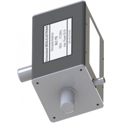
Schwarzbeck HLC 170 Monopole Antenna
-
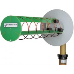
Schwarzbeck HLX 0810-LHCP Helix Antenna
-

Schwarzbeck HLX 0810-RHCP Helix Antenna
-
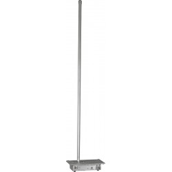
Schwarzbeck VAMP 9243 Vertical Active Rod Antenna
-
Schwarzbeck NMHA 6M Antenna Set
-
Schwarzbeck PCD 2440 Compact Monopole Antenna
-
Schwarzbeck RS 9244 Radiation Source
-
Schwarzbeck BBHA 9120 J Broadband High Gain Horn Antenna