
No products
Product successfully added to your shopping cart
There are 0 items in your cart. There is 1 item in your cart.
Schwarzbeck Automotive Antennas
- EMC Test Equipment
- Transient Generators
- RF Power Amplifiers
- DC - 300 kHz RF Amplifiers
- 10 kHz - 250 MHz RF Amplifiers
- 10 kHz - 400 MHz RF Amplifiers
- 10 kHz - 1 GHz RF Amplifiers
- 80 MHz - 1 GHz RF Amplifiers
- 1 GHz - 2 GHz RF Amplifiers
- 700 MHz - 4.2 GHz RF Amplifiers
- 1 GHz - 6 GHz RF Amplifiers
- 2 GHz - 8 GHz RF Amplifiers
- 6 GHz - 18 GHz RF Amplifiers
- 18 GHz - 40 GHz RF Amplifiers
- Pulse Amplifiers
- RF Field Strength Probes & Meters
- RF Conducted Immunity
- EMC Receivers/EMI Analyzers
- EMC Antennas
- Coupling Decoupling Networks (CDN's)
- Line Impedance Stabilization Networks (LISN's)
- RF Test Equipment
- EMC Probes
- EMC Measurement & Equipment Software
- Power Supplies
- Electrical Safety Analyzers
- High Precision Laboratory Power Analyzers & Meters
- Anechoic Chambers
- Over-the-Air (OTA) Test Chambers
- EMI RF Shielded Tent Enclosures
- RF Shielded Rooms
- EMC Absorber
- Positioning Equipment
- EMC/EMI Test Setup
- GTEM Cells / TEM Cells
- Reverberation Chambers
- Used RF Anechoic Chambers
- EMC Chamber Filters
- EMC Chamber Shielding Gaskets
- RF Shielded Doors
- Anechoic Chamber Accessories
- Fully Anechoic (FAR) Test Chambers
- Manufacturers
- 3ctest
- AE Techron
- AH Systems
- Amplifier Research
- Boonton
- Com-Power
- Diamond Engineering
- EM Test (Ametek CTS)
- EMC Partner
- EMC Test Design
- Empower High Power RF Amplifiers
- ETS-lindgren
- Log Periodic Dipole Array Antenna
- Near Field Probe Sets
- Double Ridge Horn Antennas
- Biconical Antennas
- Quad Ridge Horn Antennas
- Electric Field Probes
- GTEM's
- Positioners & Tripods
- Loop Antennas
- Biconilog Antennas
- LISN's (Line Impedance Stabilization Network)
- Shielded Enclosures/Rooms
- Monopole Antennas
- Field Generating Antennas
- Fischer Custom Communications
- Haefely Hipotronics
- Haefely EFT/Burst Immunity Test Systems
- Haefely Surge Combination Wave Test Systems
- Haefely Surge Damped Oscillating Wave Test Systems
- Haefely Electrostatic Discharge Test Systems (ESD)
- Haefely Surge Ring Wave Test Systems
- Haefely Surge Telecom Wave Test Systems
- Haefely Magnetic Field Test Systems
- Haefely CDN's (Coupling/Decoupling Networks)
- IFI Amplifiers
- Keysight (Agilent)
- MVG - Microwave Vision Group
- PMM / Narda
- Rohde & Schwarz RF Test Equipment
- Rohde & Schwarz Broadband RF Amplifiers
- Rohde & Schwarz Spectrum Analyzers
- Rohde & Schwarz Compliant EMI Test Receivers
- Rohde & Schwarz Isotropic RF Probes
- Rohde & Schwarz RF Signal Generators
- Rohde & Schwarz RF Switches
- Rohde & Schwarz Oscilloscopes
- Rohde & Schwarz RF Power Meters
- Rohde & Schwarz RF Power Sensors
- Schloder
- Schwarzbeck Mess-Elektronik
- Schwarzbeck Antennas
- Schwarzbeck Automotive Antennas
- Schwarzbeck Broadband Horn Antennas
- Schwarzbeck Biconical Antennas
- Schwarzbeck Logarithmic Periodic Broadband Antennas
- Schwarzbeck Stacked Log-Periodic Broadband Antennas
- Schwarzbeck Biconic Log-Periodic Antennas
- Schwarzbeck Dipole Antennas
- Schwarzbeck Rod Antennas
- Schwarbeck Antenna Baluns / Holders
- Schwarzbeck LISN Line Impedance Stabilisation Networks
- Schwarbeck Decoupling & Absorbing Clamps
- Schwarzbeck Field Probes
- Schwarzbeck Helmholtz Coils
- Schwarzbeck Antenna Masts
- Schwarzbeck Coupling/Decoupling Networks
- Schwarzbeck Antennas
- Solar Electronics
- Teseq (Schaffner)
- Teseq Automotive Transient Generators
- Teseq RF Test Equipment
- Teseq EFT/Burst Generators
- Teseq RF Immunity Generators
- Teseq ESD Guns
- Teseq Surge Generators
- Teseq Harmonics & Flicker Solutions
- Teseq Dips, Interrupts & Variations Equipment
- Teseq Ring Wave Generators
- Teseq Oscillatory Waves Generators
- Teseq Absorbing Clamps / Ferrite Tube
- Teseq EMC Antennas
- Teseq Current Probes
- Teseq Coupling Networks
- Thermo Keytek
- Vicreate
- Compliance Standards
- International (IEC/EN)
- EN/IEC 61000-3-2
- EN/IEC 61000-3-3
- IEC 61000-3-11
- IEC / EN 610000-3-12
- EN/IEC 61000-4-2
- EN/IEC 61000-4-3
- EN/IEC 61000-4-4
- EN/IEC 61000-4-5
- EN/IEC 61000-4-6
- EN/IEC 61000-4-7
- EN/IEC 61000-4-8
- EN/IEC 61000-4-9
- EN/IEC 61000-4-10
- EN/IEC 61000-4-11
- EN/IEC 61000-4-12
- EN/IEC 61000-4-16
- EN/IEC 61000-4-18
- EN/IEC 61000-4-19
- EN/IEC 61000-4-20
- EN/IEC 61000-4-21
- EN/IEC 61000-4-29
- EN/IEC 61000-4-31
- IEC 61000-4-39
- EN/IEC 62132
- SEMI F47 Voltage Sag Immunity
- Product Standards
- Military & Aerospace Standards
- Automotive EMC Standards
- CISPR Standards
- Telecom Testing
- ANSI/IEEE Standards
- FCC Part 15
- FCC Part 30
- International (IEC/EN)
- Application/Test Type
- Radiated Immunity
- Bulk Current Injection Testing
- RF Emissions Testing
- Conducted Immunity
- Conducted Emissions
- Antenna Pattern Measurement
- CE Mark Testing
- Intentional Radiator Testing
- Pulsed HIRF Radar
- Over-the-Air (OTA) Testing
- 5G Test Solutions
- Automotive EMC
- SAR Measurement Equipment
- Radiated Emissions
- Battery Simulator Test Equipment
- Services
- Clearance
Viewed products
-

Schwarzbeck 422 NJ...
Combination of the Flat Elements 422...
-

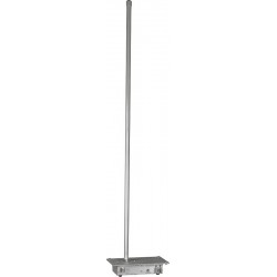
Schwarzbeck VPMP 9242...
10 - 40 MHz Vertical Passive Rod...
 View larger
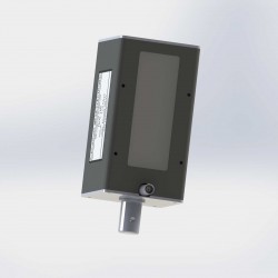
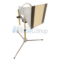
Schwarzbeck 422 NJ Flat Elements for SBA 9119
New
- Combination of the Flat Elements 422 NJ with SBA 9119-Balun
- Provides Remarkable Fieldstrength Levels with Moderate Transmit Power
- With approx. 10 Watt transmit power one can reach fieldstrength levels of 300 V/m at a distance of 30 mm
PDF Downloads
Test Equipment Description
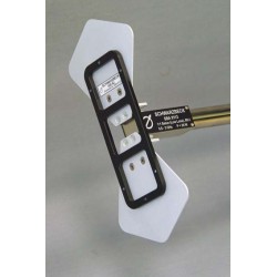
After the very successful introduction of nearfield immunity testing with SBA 9113 and the flat elements 420NJ a demand for higher frequencies arose. While the 420NJ-elements are used from 360 MHz to 2.7 GHz, there are now flat elements available, which are covering the frequency range from 800 MHz to 6 GHz. The 422NJ-elements are fed using the balun of the SBA 9119 biconical antenna. Instead of the conical elements spacer sleeves and the flat 422NJ-elements elements are used. A high quality plastic bar is used as a fixation of the flat elements in both ways, parallel and perpendicular to the balun rod. Two knurled nuts are used to connect the radiating elements with the symmetrical feed terminals of the SBA 9119 balun.
Further the elements are equipped with a spacer, which provides a repeatable spacing of 5 mm to the EuT's surface. The change of conical elements to flat ones or vice versa requires only a simple screwdriver and is typically done within two minutes. The flat elements can be arranged perpendicular or parallel to the mounting tube of SBA 9119, depending on the available space in the respective application.

Flat Elements in Perpendicular Alignment
Application:
The combination of SBA 9119-Balun with the flat elements 422NJ provides remarkable fieldstrength levels with moderate transmit power. With approx. 10 Watt transmit power one can reach fieldstrength levels of 300 V/m at a distance of 30 mm. This requires only a small adjustment of power over a wide frequency range. The recommended spacing between EuT-surface and 422NJ-elements is 30 mm. This spacing provides both, a high efficiency and good field uniformity. In most applications the EuT-surface is divided into a square shaped mesh, with the mesh width depending on the desired field uniformity. For each mesh crossing two frequency sweeped measurements with orthogonal polarisations are done. This procedure has to be repeated for each remaining mesh crossing, until the whole EuT-surface has been covered. Recommended mesh widths are around 30 to 50 mm.

Field Uniformity
The measurement of the field uniformity has been made with linear polarized single axis miniature fieldprobes, which have been especially designed for this dedicated application. In order to obtain meaningful results at close proximities, the size of the used probe must be as small as possible. The size is important for several reasons: the coupling capacitance between miniature probe and 422NJ-elements should be as low as possible, especially at short distances, otherwise the absolute fieldstrength reference becomes inaccurate. In order to achieve a satisfying spatial resolution, the probe size has to be small enough to resolve a spatial step size of 10 mm. For the measurement of the following diagrams the miniature probe was scanned in x- an y-direction (xy-plane in 10 mm steps each and at a constant distance d.
This means that the miniature probe was scanned in a parallel plane to the xy-plane over an area of 12 cm x 20 cm, separated by the constant distance of d= 25 mm. The horizontal axis shows the x-coordinate of the probe, the vertical axis the y-coordinate with the relative fieldstrength value indicated as color. All diagrams come with identical color scale, which is normalized to 0 dB. The normalisation was made with the miniature probe being centered in front of the 422NJ-elements.
The readability is improved by contour lines, which are available for relative fieldstrength levels of -3 dB, -6 dB and -10 dB. There is field uniformity data available in another file from distances between d = 10 mm up to d = 50 mm in 10 mm spacing-increments. On the following pages a field uniformity example for the distance of d = 25 mm with frequency steps of 200 MHz from 1 GHz to 6 GHz is given. The reference plane to measure the distance is the aluminium surface of the 422NJ-elements, which faces towards the EuT.

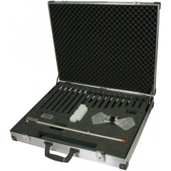
Fig. 1: Scope of Delivery of the 422NJ-elements

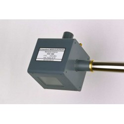
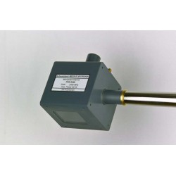
Fig. 2: SBA 9119-Balun with conical elements

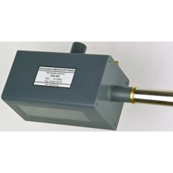
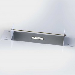
Fig. 3: SBA 9119 Balun with spacer sleeves and knurled nuts attached
General
The flat elements 422NJ (Fig. 1) consist of several parts, which have to be individually adapted to the respective SBA 9119 (Fig. 2). This first-time adaption must be made carefully in order to avoid damage of the components in use. If 422NJ and SBA 9119 were ordered together, the adaption was made in our factory before shipment. The high frequency limit of 6 GHz (wavelength 5 cm only) requires on the one hand side a certain degree of filigree work, on the other hand side a mechanical collision of the elements with the EuT surface may be possible in a real life test scenario. A correct adaption of the flat elements to the balun helps to absorb the energy of an mechanical impact on two ways, by the balun mounting tube and the element feedpoints. Therefore it is important to adapt the 422NJ elements once to the SBA 9119 balun to avoid inner mechanical stress, caused by tightening the screws. The maximum torque for plastic screws M3 is 6 Ncm and for plastic screws M4 we have 12 Ncm.
Mounting the 422NJ flat elements at the SBA 9119 Balun
- Unscrew the conical elements from SBA 9119
- Attach the two spacer sleeves
- Attach the two knurled nuts and take care for a sufficient gap to the spacer sleeves (Fig.3)
- Connect the 422NJ flat elements to the black U-shaped plastic bar using plastic screws M3 x 8 (Fig. 2)
- Place the L-shaped aluminium angles carefully in the spacing between the curled knobs and the spacer sleeves, increase the spacing by opening the nuts if required. In case the spacing is too tight at the inner side of the L-shaped aluminium angles, loosen the 4 plastic screws slightly at the connection bar between the flat elements (do not remove) and try again (Fig. 3)
- Attach the plastic clamp of the Ushaped plastic bar gently
- After all parts have found their correct position, finger-tighten the screws in the following order from inside to outside:
- First tighten the knurled nuts at the feedpoint
- If opened at all, lock the 4 plastic screws at the connection bar of the flat elements
- Finger-tighten the plastic screws to fix the flat elements to the Ushaped plastic bar
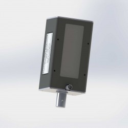
- Lock the plastic screws M4 x 16 at the clamp (Fig. 4)
The 422NJ-elements are now ready to use. In some cases with rare space it may be advantageous to mount the flat elements parallel to the mounting tube. This can be achieved by opening the two plastic screws M 3 x 8 at the flat elements and to loosen the knurled nuts at the feedpoint. The U-shaped plastic bar can remain unchanged in its position. The flat elements are mounted in parallel to the mounting tube at the U-shaped plastic bar and finally the knurled nuts are closed.

Fig. 4: U-shaped plastic bar with flat elements prior to be pushed in


Change of antenna elements
When changing the antenna elements from the 422NJ-flat elements to the original conical-elements make sure that all parts of the 422NJ-elements are removed. Often two spacer sleeves of the 422NJelements are forgotten (see Fig. 3 and 7). The spacer sleeves lead to a degradation of the VSWR with conical-elements (see Figure 8).

Fig. 8: VSWR diagram SBA 9119
| Specifications | |
| Required Balun | SBA 9119 |
| Connector | N |
| Frequency Range | 800 MHz ... 6 GHz |
| Nominal Impedance | 50 Ω |
| Continuous Power | 20 W |
| VSWR | < 8 (0.9 GHz < f < 2.4 GHz) < 4 (2.4 GHz < f < 6 GHz) |
| Material | Aluminium |
| Flat Element Dimensions | 108 x 49 x 2 mm |
| Weight | 50 g |
| Recommended Spacing | 30 mm |
| Recommended mesh width | 30 - 50 mm |
| Options | Spacer 30 mm |
| Other Spacers on request | |
18 other products in the same category:
-
Schwarzbeck 420 NJ Elements For SBA 9113 Balun
-
Schwarzbeck EGG 1860 Antenna
-
Schwarzbeck EGG 900 Antenna
-
Schwarzbeck FAN 405 Monopole Antenna
-
Schwarzbeck FAN 450 Monopole Antenna
-
Schwarzbeck FMZB 1513 Active Receive Loop Antenna
-
Schwarzbeck FMZB 1519 Active Receive Loop Antenna
-
Schwarzbeck FMZB 1519 B Active Receive Loop Antenna
-
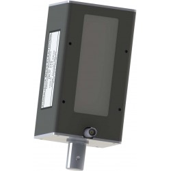
Schwarzbeck HLC 146 Monopole Antenna
-
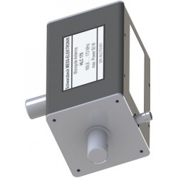
Schwarzbeck HLC 170 Monopole Antenna
-
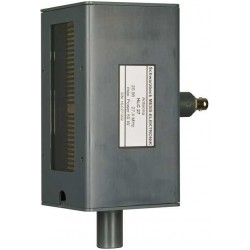
Schwarzbeck HLC 27 Dipole Antenna
-
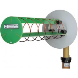
Schwarzbeck HLX 0810-LHCP Helix Antenna
-

Schwarzbeck HLX 0810-RHCP Helix Antenna
-
Schwarzbeck VAMP 9243 Vertical Active Rod Antenna
-
Schwarzbeck NMHA 6M Antenna Set
-
Schwarzbeck PCD 2440 Compact Monopole Antenna
-
Schwarzbeck RS 9244 Radiation Source
-
Schwarzbeck BBHA 9120 J Broadband High Gain Horn Antenna