
No products
Product successfully added to your shopping cart
There are 0 items in your cart. There is 1 item in your cart.
Schwarzbeck Biconical Antennas
- EMC Test Equipment
- Transient Generators
- RF Power Amplifiers
- DC - 300 kHz RF Amplifiers
- 10 kHz - 250 MHz RF Amplifiers
- 10 kHz - 400 MHz RF Amplifiers
- 10 kHz - 1 GHz RF Amplifiers
- 80 MHz - 1 GHz RF Amplifiers
- 1 GHz - 2 GHz RF Amplifiers
- 700 MHz - 4.2 GHz RF Amplifiers
- 1 GHz - 6 GHz RF Amplifiers
- 2 GHz - 8 GHz RF Amplifiers
- 6 GHz - 18 GHz RF Amplifiers
- 18 GHz - 40 GHz RF Amplifiers
- Pulse Amplifiers
- RF Field Strength Probes & Meters
- RF Conducted Immunity
- EMC Receivers/EMI Analyzers
- EMC Antennas
- Coupling Decoupling Networks (CDN's)
- Line Impedance Stabilization Networks (LISN's)
- RF Test Equipment
- EMC Probes
- EMC Measurement & Equipment Software
- Power Supplies
- Electrical Safety Analyzers
- High Precision Laboratory Power Analyzers & Meters
- Anechoic Chambers
- Over-the-Air (OTA) Test Chambers
- EMI RF Shielded Tent Enclosures
- RF Shielded Rooms
- EMC Absorber
- Positioning Equipment
- EMC/EMI Test Setup
- GTEM Cells / TEM Cells
- Reverberation Chambers
- Used RF Anechoic Chambers
- EMC Chamber Filters
- EMC Chamber Shielding Gaskets
- RF Shielded Doors
- Anechoic Chamber Accessories
- Fully Anechoic (FAR) Test Chambers
- Manufacturers
- 3ctest
- AE Techron
- AH Systems
- Amplifier Research
- Boonton
- Com-Power
- Diamond Engineering
- EM Test (Ametek CTS)
- EMC Partner
- EMC Test Design
- Empower High Power RF Amplifiers
- ETS-lindgren
- Log Periodic Dipole Array Antenna
- Near Field Probe Sets
- Double Ridge Horn Antennas
- Biconical Antennas
- Quad Ridge Horn Antennas
- Electric Field Probes
- GTEM's
- Positioners & Tripods
- Loop Antennas
- Biconilog Antennas
- LISN's (Line Impedance Stabilization Network)
- Shielded Enclosures/Rooms
- Monopole Antennas
- Field Generating Antennas
- Fischer Custom Communications
- Haefely Hipotronics
- Haefely EFT/Burst Immunity Test Systems
- Haefely Surge Combination Wave Test Systems
- Haefely Surge Damped Oscillating Wave Test Systems
- Haefely Electrostatic Discharge Test Systems (ESD)
- Haefely Surge Ring Wave Test Systems
- Haefely Surge Telecom Wave Test Systems
- Haefely Magnetic Field Test Systems
- Haefely CDN's (Coupling/Decoupling Networks)
- IFI Amplifiers
- Keysight (Agilent)
- MVG - Microwave Vision Group
- PMM / Narda
- Rohde & Schwarz RF Test Equipment
- Rohde & Schwarz Broadband RF Amplifiers
- Rohde & Schwarz Spectrum Analyzers
- Rohde & Schwarz Compliant EMI Test Receivers
- Rohde & Schwarz Isotropic RF Probes
- Rohde & Schwarz RF Signal Generators
- Rohde & Schwarz RF Switches
- Rohde & Schwarz Oscilloscopes
- Rohde & Schwarz RF Power Meters
- Rohde & Schwarz RF Power Sensors
- Schloder
- Schwarzbeck Mess-Elektronik
- Schwarzbeck Antennas
- Schwarzbeck Automotive Antennas
- Schwarzbeck Broadband Horn Antennas
- Schwarzbeck Biconical Antennas
- Schwarzbeck Logarithmic Periodic Broadband Antennas
- Schwarzbeck Stacked Log-Periodic Broadband Antennas
- Schwarzbeck Biconic Log-Periodic Antennas
- Schwarzbeck Dipole Antennas
- Schwarzbeck Rod Antennas
- Schwarbeck Antenna Baluns / Holders
- Schwarzbeck LISN Line Impedance Stabilisation Networks
- Schwarbeck Decoupling & Absorbing Clamps
- Schwarzbeck Field Probes
- Schwarzbeck Helmholtz Coils
- Schwarzbeck Antenna Masts
- Schwarzbeck Coupling/Decoupling Networks
- Schwarzbeck Antennas
- Solar Electronics
- Teseq (Schaffner)
- Teseq Automotive Transient Generators
- Teseq RF Test Equipment
- Teseq EFT/Burst Generators
- Teseq RF Immunity Generators
- Teseq ESD Guns
- Teseq Surge Generators
- Teseq Harmonics & Flicker Solutions
- Teseq Dips, Interrupts & Variations Equipment
- Teseq Ring Wave Generators
- Teseq Oscillatory Waves Generators
- Teseq Absorbing Clamps / Ferrite Tube
- Teseq EMC Antennas
- Teseq Current Probes
- Teseq Coupling Networks
- Thermo Keytek
- Vicreate
- Compliance Standards
- International (IEC/EN)
- EN/IEC 61000-3-2
- EN/IEC 61000-3-3
- IEC 61000-3-11
- IEC / EN 610000-3-12
- EN/IEC 61000-4-2
- EN/IEC 61000-4-3
- EN/IEC 61000-4-4
- EN/IEC 61000-4-5
- EN/IEC 61000-4-6
- EN/IEC 61000-4-7
- EN/IEC 61000-4-8
- EN/IEC 61000-4-9
- EN/IEC 61000-4-10
- EN/IEC 61000-4-11
- EN/IEC 61000-4-12
- EN/IEC 61000-4-16
- EN/IEC 61000-4-18
- EN/IEC 61000-4-19
- EN/IEC 61000-4-20
- EN/IEC 61000-4-21
- EN/IEC 61000-4-29
- EN/IEC 61000-4-31
- IEC 61000-4-39
- EN/IEC 62132
- SEMI F47 Voltage Sag Immunity
- Product Standards
- Military & Aerospace Standards
- Automotive EMC Standards
- CISPR Standards
- Telecom Testing
- ANSI/IEEE Standards
- FCC Part 15
- FCC Part 30
- International (IEC/EN)
- Application/Test Type
- Radiated Immunity
- Bulk Current Injection Testing
- RF Emissions Testing
- Conducted Immunity
- Conducted Emissions
- Antenna Pattern Measurement
- CE Mark Testing
- Intentional Radiator Testing
- Pulsed HIRF Radar
- Over-the-Air (OTA) Testing
- 5G Test Solutions
- Automotive EMC
- SAR Measurement Equipment
- Radiated Emissions
- Battery Simulator Test Equipment
- Services
- Clearance
Viewed products
-

Schwarzbeck UBA 9116...
(160) 300 -1000 (1100) MHz Biconical...
-

EM Test AMP 200N Low...
Built-in DDS to generate sinusoidal...
 View larger
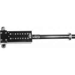
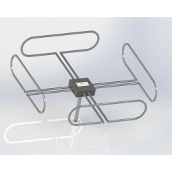
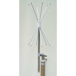
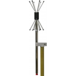
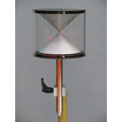
Schwarzbeck UBA 9116 Biconical UHF Broadband Antenna
New
- (160) 300 -1000 (1100) MHz
- Biconical UHF broadband antenna
PDF Downloads
Test Equipment Description

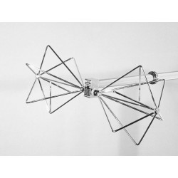
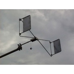
Both for the measurement of Field Strengths and for the generation of defined Electromagnetic Fields (EMC) in the UHF range 300 MHz to 1 GHz a number of different antenna systems may be useful: Tuneable Half-Wave Dipoles (UHA 9105), Precision Dipoles UHAP, Log. -Periodic Antennas (UHALP 9108 A, VULP 9118 and more), Horn Antennas (BBHA 9120) and Standard Gain Antennas, and shown here, BICONICALS.
Gain Antennas reduce errors by unwanted reflections, but their disadvantage in most cases is the frequency-dependent phase center, due to a non-circular H-pattern the ray to the ground reflection point may be of reduced intensity compared to the direct ray. Half-Wave Dipoles are often used as reference antennas. Their disadvantage with economical testing is the need for element adjustment with every frequency change (no automatic testing). In the VHF range the Biconical Broadband Antennas (BBA 9106 in holder/balun VHA 9103 or VHBA 9123) are in wide-spread use worldwide, they can be found on almost every antenna testing range or EMI/EMC Test Houses. With gain and antenna factor in the main frequency range (300-1000 MHz) they have similar gain and antenna factor figures as half-wave dipoles, but do not require any adjustment. They possess a circular H pattern and a fixed phase center, important for short test sites.
The Biconical UHF Broadband Antenna UBA 9116 shown here offers these attractive features in the UHF range (300 MHz - 1 GHz). With higher antenna factors (negative gain dBi) they may be used down to 160 MHz and up to 1.3 GHz.
As this antenna radiates or receives perpendicular to the dipole plane into all directions, economical testing set-ups with two or more simultaneous functions are possible.
Schwarzbeck UBA 9116 Application as an E Field Sensor
For the measurement of E field-strength in the volt-per-meter region diode or FET sensors with short dipoles are frequently used. They offer wide bandwidths and reasonable flatness, but the accuracy for a defined frequency is limited. A calibration is usually performed in TEM cells. Their vertical width should be 5 times the length of the test dipole to obtain sufficient accuracy. In case of a Crawford triplate cell the total height would be ten times the dipole length. Such large TEM cells suffer from a frequency limit in the vhf range. For EMC applications a calibration up to 1 GHz should be possible.
The passive biconical Test Antenna UBA 9116 has primarily been designed for field-strength measurements in the range 300 MHz to 1 GHz, but may be used with dipole-like antenna factors between 200 MHz and 1.3 GHz. Such passive antennas with identical gain data can be accurately calibrated under free-space conditions with the "Two-Antenna-Method" that does n o t require a gain standard. The measurement uncertainty can be reduced to less than 1 dB under near-perfect freespace conditions using a method developed here with simultaneous height-variation and averaging the results.
The aim of designing E field sensors might be a very short dipole length to measure the fieldstrength on a defined "spot". In case of immunity testing of practical equipment, e.g. of 19" boxes, the surface or volume of the EuT must be tested. In case of varying field-strengths a final definition must be established. An alternative method could be the use of an E field sensor of a comparable size compared to the EuT. With a total length of the biconical antenna of 325 mm this condition is met for a number of applications
One of these applications is the field-strength measurement at a separation of 3m in front of the tip of a logarithmic-periodic antenna for immunity testing such as IEC 801-3,IEC 1000-4-3, ENV 50140, VDE 0847, part 3, also EN 50147.
The calibration of the model UBA 9116 has been extended down to the low limit of the vhf band (25 MHz). The antenna factor with a minimum at 300 MHz rises again with lower frequences. As the application is with high field strengths and sensitive test receivers are available for EMI testing, low f.s. levels down to 1 mV/m at 25 MHz can be measured.
In these applications a perfect shielding should be provided for coaxial cables and the test receiver because any signal interception would add to the (relatively low) voltage from the test antenna. As the VSWR of the antenna will be high at such low frequencies (far off resonance), the test receiver input impedance should be 50 W resistive. This situation may be improved with vhf fixed attenuators of 6 dB or 10 dB between antenna output and coaxial cable
| Schwarzbeck UBA 9116 Specifications | |
| Frequency Range (useable) | 160 - 1100 MHz |
| Main Frequency Range | 300 - 1000 MHz |
| Isotropic Gain | + 1.3 dBi ... -1.4 dBi |
| Gain over l/2 Dipole | - 0.9 dBd ... -3.6 dBd |
| Return loss f > 250 MHz | typ. 4 dB |
| Ret. loss f > 250 MHz, 3 dB pad | typ. 10 dB » SWR 2 |
| Antenna Factor | 18 - 30 dB/m |
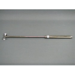
| Dimensions | Length holder:520 mm |
| Length holder with cones | 570 mm |
| Width | 325 mm |
| Antenna shaft (Tube) | Æ 22 mm |
| Total weight | 0.83 kg |
| Power (EMC TX) | 5 W |
| Coaxial Connector | N-Buchse / N - female |
16 other products in the same category:
-
Schwarzbeck VHBC 9133 High Power Broadband Balun
-
Schwarzbeck BBVK 9138 Biconical Elements in Balun VHA 9103
-
Schwarzbeck SBA 9112 Microwave Biconical Broadband Antenna
-
Schwarzbeck RSH 4786 Horizontal Polarised Omnidirectional UHF Antenna
-
Schwarzbeck RSH 2342 Horizontal Polarised Omnidirectional VHF Antenna
-
Schwarzbeck RSAL 5340 Low Frequency Rolling Stock Antenna
-
Schwarzbeck RSAH 5324 High Frequency Rolling Stock Antenna
-
Schwarzbeck SBA 9113 Microwave Biconical Antenna
-

Schwarzbeck SBA 9113 B Microwave Biconical Antenna
-
Schwarzbeck SBA 9119 Microwave Biconical Broadband Antenna
-
Schwarzbeck RE 1790 VHF-UHF Omnidirectional Antenna
-
Schwarzbeck RE 4590 VHF-UHF Omnidirectional Antenna
-
Schwarzbeck RS 16 Omnidirectional Antenna 1-6 GHz
-
Schwarzbeck RS 0460 Biconical Omnidirectional Antenna 0.4 - 6 GHz
-
Schwarzbeck VUBA 9117 VHF-UHF Biconical Antenna
-
Schwarzbeck BBAE 9179 Foldable Radiating Elements for Immunity Tests