
No products
Product successfully added to your shopping cart
There are 0 items in your cart. There is 1 item in your cart.
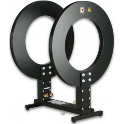
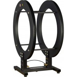
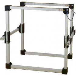
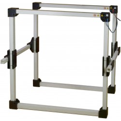
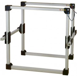
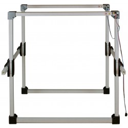
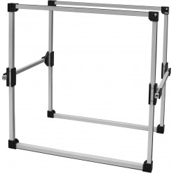
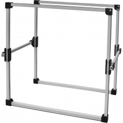
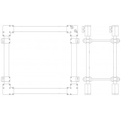
Schwarzbeck Helmholtz Coils
- EMC Test Equipment
- Transient Generators
- RF Power Amplifiers
- DC - 300 kHz RF Amplifiers
- 10 kHz - 250 MHz RF Amplifiers
- 10 kHz - 400 MHz RF Amplifiers
- 10 kHz - 1 GHz RF Amplifiers
- 80 MHz - 1 GHz RF Amplifiers
- 1 GHz - 2 GHz RF Amplifiers
- 700 MHz - 4.2 GHz RF Amplifiers
- 1 GHz - 6 GHz RF Amplifiers
- 2 GHz - 8 GHz RF Amplifiers
- 6 GHz - 18 GHz RF Amplifiers
- 18 GHz - 40 GHz RF Amplifiers
- Pulse Amplifiers
- RF Field Strength Probes & Meters
- RF Conducted Immunity
- EMC Receivers/EMI Analyzers
- EMC Antennas
- Coupling Decoupling Networks (CDN's)
- Line Impedance Stabilization Networks (LISN's)
- RF Test Equipment
- EMC Probes
- EMC Measurement & Equipment Software
- Power Supplies
- Electrical Safety Analyzers
- High Precision Laboratory Power Analyzers & Meters
- Anechoic Chambers
- Over-the-Air (OTA) Test Chambers
- EMI RF Shielded Tent Enclosures
- RF Shielded Rooms
- EMC Absorber
- Positioning Equipment
- EMC/EMI Test Setup
- GTEM Cells / TEM Cells
- Reverberation Chambers
- Used RF Anechoic Chambers
- EMC Chamber Filters
- EMC Chamber Shielding Gaskets
- RF Shielded Doors
- Anechoic Chamber Accessories
- Fully Anechoic (FAR) Test Chambers
- Manufacturers
- 3ctest
- AE Techron
- AH Systems
- Amplifier Research
- Boonton
- Com-Power
- Diamond Engineering
- EM Test (Ametek CTS)
- EMC Partner
- EMC Test Design
- Empower High Power RF Amplifiers
- ETS-lindgren
- Log Periodic Dipole Array Antenna
- Near Field Probe Sets
- Double Ridge Horn Antennas
- Biconical Antennas
- Quad Ridge Horn Antennas
- Electric Field Probes
- GTEM's
- Positioners & Tripods
- Loop Antennas
- Biconilog Antennas
- LISN's (Line Impedance Stabilization Network)
- Shielded Enclosures/Rooms
- Monopole Antennas
- Field Generating Antennas
- Fischer Custom Communications
- Haefely Hipotronics
- Haefely EFT/Burst Immunity Test Systems
- Haefely Surge Combination Wave Test Systems
- Haefely Surge Damped Oscillating Wave Test Systems
- Haefely Electrostatic Discharge Test Systems (ESD)
- Haefely Surge Ring Wave Test Systems
- Haefely Surge Telecom Wave Test Systems
- Haefely Magnetic Field Test Systems
- Haefely CDN's (Coupling/Decoupling Networks)
- IFI Amplifiers
- Keysight (Agilent)
- MVG - Microwave Vision Group
- PMM / Narda
- Rohde & Schwarz RF Test Equipment
- Rohde & Schwarz Broadband RF Amplifiers
- Rohde & Schwarz Spectrum Analyzers
- Rohde & Schwarz Compliant EMI Test Receivers
- Rohde & Schwarz Isotropic RF Probes
- Rohde & Schwarz RF Signal Generators
- Rohde & Schwarz RF Switches
- Rohde & Schwarz Oscilloscopes
- Rohde & Schwarz RF Power Meters
- Rohde & Schwarz RF Power Sensors
- Schloder
- Schwarzbeck Mess-Elektronik
- Schwarzbeck Antennas
- Schwarzbeck Automotive Antennas
- Schwarzbeck Broadband Horn Antennas
- Schwarzbeck Biconical Antennas
- Schwarzbeck Logarithmic Periodic Broadband Antennas
- Schwarzbeck Stacked Log-Periodic Broadband Antennas
- Schwarzbeck Biconic Log-Periodic Antennas
- Schwarzbeck Dipole Antennas
- Schwarzbeck Rod Antennas
- Schwarbeck Antenna Baluns / Holders
- Schwarzbeck LISN Line Impedance Stabilisation Networks
- Schwarbeck Decoupling & Absorbing Clamps
- Schwarzbeck Field Probes
- Schwarzbeck Helmholtz Coils
- Schwarzbeck Antenna Masts
- Schwarzbeck Coupling/Decoupling Networks
- Schwarzbeck Antennas
- Solar Electronics
- Teseq (Schaffner)
- Teseq Automotive Transient Generators
- Teseq RF Test Equipment
- Teseq EFT/Burst Generators
- Teseq RF Immunity Generators
- Teseq ESD Guns
- Teseq Surge Generators
- Teseq Harmonics & Flicker Solutions
- Teseq Dips, Interrupts & Variations Equipment
- Teseq Ring Wave Generators
- Teseq Oscillatory Waves Generators
- Teseq Absorbing Clamps / Ferrite Tube
- Teseq EMC Antennas
- Teseq Current Probes
- Teseq Coupling Networks
- Thermo Keytek
- Vicreate
- Compliance Standards
- International (IEC/EN)
- EN/IEC 61000-3-2
- EN/IEC 61000-3-3
- IEC 61000-3-11
- IEC / EN 610000-3-12
- EN/IEC 61000-4-2
- EN/IEC 61000-4-3
- EN/IEC 61000-4-4
- EN/IEC 61000-4-5
- EN/IEC 61000-4-6
- EN/IEC 61000-4-7
- EN/IEC 61000-4-8
- EN/IEC 61000-4-9
- EN/IEC 61000-4-10
- EN/IEC 61000-4-11
- EN/IEC 61000-4-12
- EN/IEC 61000-4-16
- EN/IEC 61000-4-18
- EN/IEC 61000-4-19
- EN/IEC 61000-4-20
- EN/IEC 61000-4-21
- EN/IEC 61000-4-29
- EN/IEC 61000-4-31
- IEC 61000-4-39
- EN/IEC 62132
- SEMI F47 Voltage Sag Immunity
- Product Standards
- Military & Aerospace Standards
- Automotive EMC Standards
- CISPR Standards
- Telecom Testing
- ANSI/IEEE Standards
- FCC Part 15
- FCC Part 30
- International (IEC/EN)
- Application/Test Type
- Radiated Immunity
- Bulk Current Injection Testing
- RF Emissions Testing
- Conducted Immunity
- Conducted Emissions
- Antenna Pattern Measurement
- CE Mark Testing
- Intentional Radiator Testing
- Pulsed HIRF Radar
- Over-the-Air (OTA) Testing
- 5G Test Solutions
- Automotive EMC
- SAR Measurement Equipment
- Radiated Emissions
- Battery Simulator Test Equipment
- Services
- Clearance
Viewed products
-

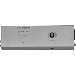
Schwarzbeck NFCN...
DC - 150 kHz Frequency Range 1 Ohm /...
 View larger
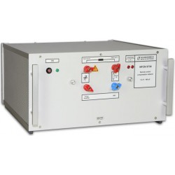
Schwarzbeck NFCN 9731-100 Compensation Network
New
- DC - 150 kHz Frequency Range
- 1 Ohm / 800 W Integrated Shunt
- Max continuous current: up to 32 Arms
- Capacitance range: 1.5 nF - 300 µF
- Provide a serial compensation of the inductance of the HHS 5206-16
PDF Downloads
Test Equipment Description
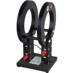
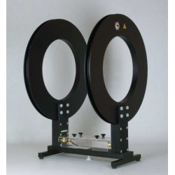
The primary function of the compensation network NFCN 9731-100 is to provide a serial compensation of the inductance of i.e. the HHS 5230 at operation frequencies of 16.666 Hz, 50 Hz, 60 Hz, 150 Hz und 180 Hz. These operation frequencies are stipulated by SAE J551-17 (Vehicle Electromagnetic Immunity – Power Line Magnetic Fields).
The NFCN 9731-100 provides two separate channels utilizing a shared control unit. Thus every single coil of the Helmholtz coil is powered by a separate amplifier. The current flowing through the coils can be checked using the built-in RMS-ampere-meters.
The compensation capacitor reduces the overall impedance of the series circuit consisting of the Helmholtz coil HHS 5230 and the compensation network NFCN 9731-100 at the applied operating frequency and allows currents up to 8 Arms at a generator voltage of less than 60 Vrms.
To protect the amplifier and the compensation network NFCN 9731-100 is equipped with a 10 A fuse.
An overvoltage protective circuit connects a damping resistor in parallel to the capacitor when exceeding the maximum operating voltage (at currents higher than 8 Arms)
The Helmholtz coil has to be connected (eventually using a load resistance in series) to the terminals “OUTPUT” and “COMMON”. The generator (output of the amplifier) has to be connected to the terminals “INPUT” and “COMMON”. The terminal “COMMON” may be grounded.
The wiring must not be done in different order. Otherwise the protection circuit does not work!
Block Diagram of the NFCN 9731-100

The signal level has to be increased slowly until the maximum current has been reached. Abrupt overload leads to voltage spikes. The protection circuit is too slow to prevent damage in case of abrupt overload.
The NFCN 9731 has to be controlled manually.
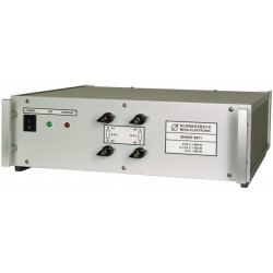
Measurement setup with a waveform generator, amplifiers, compensation network
(NFCN 9731-100) and Helmholtz coil (HHS 5230).

Operating:
Before putting the NFCN 9731-100 to operation you MUST set the voltage selector switch for the mains power to the correct value (115V/230V)! You can find the selector switch on the backside of the device on the left of the (IEC) socket.
- Turn the volume regulator of the amplifiers to minimum.
- Connect the devices to mains and switch them on.
- Set the function generator to "SIGNAL OFF"
- Adjust the level of the function generator to approx. 20…50 mV
- Turn the volume regulators of both amplifiers to approx. 80% of the maximum level.
- Set the rotary switch at the frontpanel of the NFCN 9731-100 to the required frequency.
- Adjust the required frequency to the function generator and turn „SIGNAL ON“ on.
- Slowly increase the signal level until one of the ampere-meters shows the wished current.
- Use the volume regulator of the amplifier in the other circuit to balance the currents of both amplifiers.
Important! Switching capacitors is only allowed without applying any signal. Otherwise amplifiers and compensation networks will be damaged.
Note: If the overload protection circuit is active the LED “Overload” will light up and the compensation capacitor will be damped.
In this case:
- Turn off the function generator immediately. (risk of overheating!).
- Decrease the signal level
- Turn off the NFCN 9731-100 for a moment and turn it back on again. The “Overload” LED won’t light up any longer and the compensation network will be ready to operate again.
19 other products in the same category:
-
Schwarzbeck NFCN 9732 85 kHz Compensation Network
-
Schwarzbeck NFCN 9734 Compensation Network
-
Schwarzbeck SHUNT 9571 High Power Shunt Resistor
-
Schwarzbeck HS 5136 Hall Sensor
-
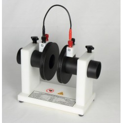
Schwarzbeck HHS 5201-6 Circular Helmholtz Coils
-
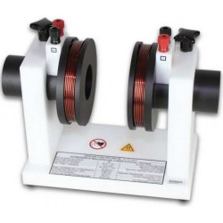
Schwarzbeck HHS 5201-98 Circular Helmholtz Coils
-
Schwarzbeck HHS 5202-81 Circular Helmholtz Coils
-
Schwarzbeck HHS 5204-12 Circular Helmholtz Coils
-
Schwarzbeck HHS 5204-36 Circular Helmholtz Coils
-
Schwarzbeck HHS 5206-132 Circular Helmholtz Coils
-

Schwarzbeck HHS 5206-16 Circular Helmholtz Coils
-

Schwarzbeck HHS 5206-8 Circular Helmholtz Coils
-
Schwarzbeck HHS 5210 Helmholtz Coils
-
Schwarzbeck HHS 5210-100 Helmholtz Coils
-
Schwarzbeck HHS 5210-100-2.5 Helmholtz Coils
-
Schwarzbeck HHS 5213-100 Helmholtz Coils
-
Schwarzbeck HHS 5215-10 Helmholtz Coils
-
Schwarzbeck HHS 5215-100 Helmholtz Coils
-
Schwarzbeck HHS 5218 Helmholtz Coils