
No products
Product successfully added to your shopping cart
There are 0 items in your cart. There is 1 item in your cart.
Schwarzbeck Helmholtz Coils
- EMC Test Equipment
- Transient Generators
- RF Power Amplifiers
- DC - 300 kHz RF Amplifiers
- 10 kHz - 250 MHz RF Amplifiers
- 10 kHz - 400 MHz RF Amplifiers
- 10 kHz - 1 GHz RF Amplifiers
- 80 MHz - 1 GHz RF Amplifiers
- 1 GHz - 2 GHz RF Amplifiers
- 700 MHz - 4.2 GHz RF Amplifiers
- 1 GHz - 6 GHz RF Amplifiers
- 2 GHz - 8 GHz RF Amplifiers
- 6 GHz - 18 GHz RF Amplifiers
- 18 GHz - 40 GHz RF Amplifiers
- Pulse Amplifiers
- RF Field Strength Probes & Meters
- RF Conducted Immunity
- EMC Receivers/EMI Analyzers
- EMC Antennas
- Coupling Decoupling Networks (CDN's)
- Line Impedance Stabilization Networks (LISN's)
- RF Test Equipment
- EMC Probes
- EMC Measurement & Equipment Software
- Power Supplies
- Electrical Safety Analyzers
- High Precision Laboratory Power Analyzers & Meters
- Anechoic Chambers
- Over-the-Air (OTA) Test Chambers
- EMI RF Shielded Tent Enclosures
- RF Shielded Rooms
- EMC Absorber
- Positioning Equipment
- EMC/EMI Test Setup
- GTEM Cells / TEM Cells
- Reverberation Chambers
- Used RF Anechoic Chambers
- EMC Chamber Filters
- EMC Chamber Shielding Gaskets
- RF Shielded Doors
- Anechoic Chamber Accessories
- Fully Anechoic (FAR) Test Chambers
- Manufacturers
- 3ctest
- AE Techron
- AH Systems
- Amplifier Research
- Boonton
- Com-Power
- Diamond Engineering
- EM Test (Ametek CTS)
- EMC Partner
- EMC Test Design
- Empower High Power RF Amplifiers
- ETS-lindgren
- Log Periodic Dipole Array Antenna
- Near Field Probe Sets
- Double Ridge Horn Antennas
- Biconical Antennas
- Quad Ridge Horn Antennas
- Electric Field Probes
- GTEM's
- Positioners & Tripods
- Loop Antennas
- Biconilog Antennas
- LISN's (Line Impedance Stabilization Network)
- Shielded Enclosures/Rooms
- Monopole Antennas
- Field Generating Antennas
- Fischer Custom Communications
- Haefely Hipotronics
- Haefely EFT/Burst Immunity Test Systems
- Haefely Surge Combination Wave Test Systems
- Haefely Surge Damped Oscillating Wave Test Systems
- Haefely Electrostatic Discharge Test Systems (ESD)
- Haefely Surge Ring Wave Test Systems
- Haefely Surge Telecom Wave Test Systems
- Haefely Magnetic Field Test Systems
- Haefely CDN's (Coupling/Decoupling Networks)
- IFI Amplifiers
- Keysight (Agilent)
- MVG - Microwave Vision Group
- PMM / Narda
- Rohde & Schwarz RF Test Equipment
- Rohde & Schwarz Broadband RF Amplifiers
- Rohde & Schwarz Spectrum Analyzers
- Rohde & Schwarz Compliant EMI Test Receivers
- Rohde & Schwarz Isotropic RF Probes
- Rohde & Schwarz RF Signal Generators
- Rohde & Schwarz RF Switches
- Rohde & Schwarz Oscilloscopes
- Rohde & Schwarz RF Power Meters
- Rohde & Schwarz RF Power Sensors
- Schloder
- Schwarzbeck Mess-Elektronik
- Schwarzbeck Antennas
- Schwarzbeck Automotive Antennas
- Schwarzbeck Broadband Horn Antennas
- Schwarzbeck Biconical Antennas
- Schwarzbeck Logarithmic Periodic Broadband Antennas
- Schwarzbeck Stacked Log-Periodic Broadband Antennas
- Schwarzbeck Biconic Log-Periodic Antennas
- Schwarzbeck Dipole Antennas
- Schwarzbeck Rod Antennas
- Schwarbeck Antenna Baluns / Holders
- Schwarzbeck LISN Line Impedance Stabilisation Networks
- Schwarbeck Decoupling & Absorbing Clamps
- Schwarzbeck Field Probes
- Schwarzbeck Helmholtz Coils
- Schwarzbeck Antenna Masts
- Schwarzbeck Coupling/Decoupling Networks
- Schwarzbeck Antennas
- Solar Electronics
- Teseq (Schaffner)
- Teseq Automotive Transient Generators
- Teseq RF Test Equipment
- Teseq EFT/Burst Generators
- Teseq RF Immunity Generators
- Teseq ESD Guns
- Teseq Surge Generators
- Teseq Harmonics & Flicker Solutions
- Teseq Dips, Interrupts & Variations Equipment
- Teseq Ring Wave Generators
- Teseq Oscillatory Waves Generators
- Teseq Absorbing Clamps / Ferrite Tube
- Teseq EMC Antennas
- Teseq Current Probes
- Teseq Coupling Networks
- Thermo Keytek
- Vicreate
- Compliance Standards
- International (IEC/EN)
- EN/IEC 61000-3-2
- EN/IEC 61000-3-3
- IEC 61000-3-11
- IEC / EN 610000-3-12
- EN/IEC 61000-4-2
- EN/IEC 61000-4-3
- EN/IEC 61000-4-4
- EN/IEC 61000-4-5
- EN/IEC 61000-4-6
- EN/IEC 61000-4-7
- EN/IEC 61000-4-8
- EN/IEC 61000-4-9
- EN/IEC 61000-4-10
- EN/IEC 61000-4-11
- EN/IEC 61000-4-12
- EN/IEC 61000-4-16
- EN/IEC 61000-4-18
- EN/IEC 61000-4-19
- EN/IEC 61000-4-20
- EN/IEC 61000-4-21
- EN/IEC 61000-4-29
- EN/IEC 61000-4-31
- IEC 61000-4-39
- EN/IEC 62132
- SEMI F47 Voltage Sag Immunity
- Product Standards
- Military & Aerospace Standards
- Automotive EMC Standards
- CISPR Standards
- Telecom Testing
- ANSI/IEEE Standards
- FCC Part 15
- FCC Part 30
- International (IEC/EN)
- Application/Test Type
- Radiated Immunity
- Bulk Current Injection Testing
- RF Emissions Testing
- Conducted Immunity
- Conducted Emissions
- Antenna Pattern Measurement
- CE Mark Testing
- Intentional Radiator Testing
- Pulsed HIRF Radar
- Over-the-Air (OTA) Testing
- 5G Test Solutions
- Automotive EMC
- SAR Measurement Equipment
- Radiated Emissions
- Battery Simulator Test Equipment
- Services
- Clearance
Viewed products
-

Schwarzbeck HHS...
DC – 30 kHz Usable Frequency Range...
 View larger
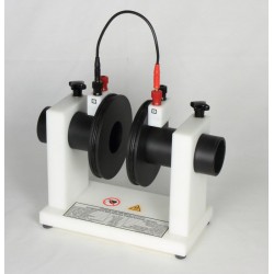
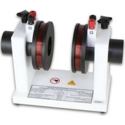
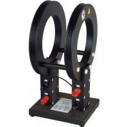
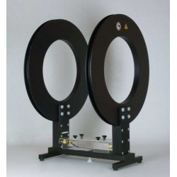
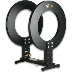
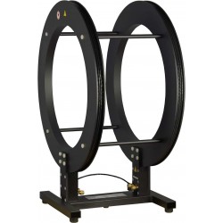
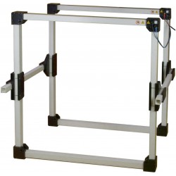
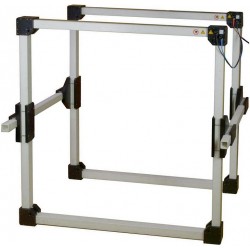
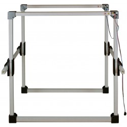
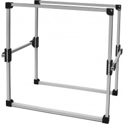
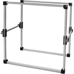
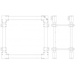
Schwarzbeck HHS 5206-132 Circular Helmholtz Coils
New
- DC – 30 kHz Usable Frequency Range
- Ideally suited for the calibration of magnetic field probes or sensors
- Designed to generate precisely defined magnetic fields;
- From DC to the upper end of the audio frequency range and beyond
- Fieldstrength can be calculated exactly by analytical (or numerical) methods
PDF Downloads
Test Equipment Description
Helmholtz-Coils are especially designed to generate precisely defined magnetic fields from DC to the upper end of the audio frequency range and beyond. The generated fields are in a strongly linear relation to the coil current. The fieldstrength can be calculated exactly by analytical (or numerical) methods, based on the coils' geometry, the number of turns and the coil current.
Therefore the HHS 5206-132 is ideally suited for the calibration of magnetic field probes or sensors. Typical applications are magnetic immunity testing according to automotive standards or MIL-461F. When generating magnetic fields with Helmholtz coils the coil current is directly proportional to the magnetic field strength. The calibration of the magnetic field is finally traceable to a current measurement (or to a voltage drop at a known resistor).
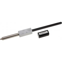
The Helmholtz Coil itself is usually considered as primary standard due to the easily calculable relation between current and field strength. If this relation should be controlled, a loop sensor or monitoring loop can be used to determine the actual field strength.
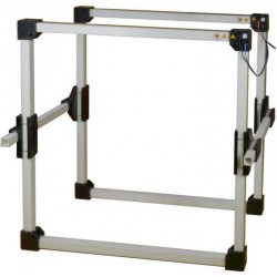
Installation
The Helmholtz-Coils should be installed on a desk in a sufficiently large separation from sources of unintentional magnetic fields, e.g. transformers in power supplies, conductors carrying high currents, computer monitors, loudspeakers, cathode ray tubes (CRT) and so on. All kinds of magnetic material (e.g. steel, nickel, cobalt) should be removed from the near surrounding of the coil. The wires which are used to connect the current source with the Helmholtz-Coil should be twisted to avoid an unwanted injection of magnetic flux.
The coil terminals are assigned with the characters A, B, C and D. The generator (current source, audio-amplifier...) is connected to the terminals A and C, the terminals B and D are connected with the short cable supplied with the coil.
An additional verification can be done by measuring the magnetic fieldstrength between the coils. Assuming a wrong connection, the fieldstrength decays very sharply in the center between the coils, because the fields compensate each other.

Typical Test Setup for Immunity against magnetic fields
| Specifications | |
| Number of turns (per Coil) | 132 |
| Maximum Coil Current | 15 A, 5 min |
| Nominal Coil Current | 10 A continuous |
| Coil Spacings | 300 mm |
| Maximum magnetic field strength | 4713 A/m, 5 min. |
| Nominal magnetic field strength | 3142 A/m continuous |
| Magnetic field strength @ 1 A Coil Current | 314.2 A/m 169.97 dBµA/m |
| Current required for 1 A/m | 3.183 mA |
| Conversion Current Fieldstrength (Coil factor) | 50 dB/m |
| Coil diameter | 600 mm |
| Mechanical dimensions | 0.64 m x 0.79 m x 0.42m |
| Max. cubical shaped DuT | 32.5x32.5x32.5 cm |
| Terminals | 4 mm banana jacks Screw terminals |
| Usable frequency range | DC - 30 kHz |
| Inductance (per coil) | 22.4 mH |
| Inductance (pair of coils) | 49.9 mH |
| Resistance by 20°C (per coil) | 1.42 Ω |
| Resistance by 120°C (per coil) | 1.96 Ω |
| Coil capacitance (pair of coils) | 174 pF |
| Resonance frequency (Pair of coils) | > 50 kHz |
| Weight | 27.5 kg |
19 other products in the same category:
-
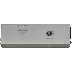
Schwarzbeck NFCN 9731-100 Compensation Network
-
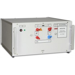
Schwarzbeck NFCN 9732 85 kHz Compensation Network
-
Schwarzbeck NFCN 9734 Compensation Network
-
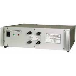
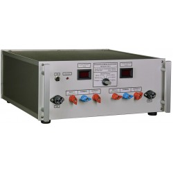
Schwarzbeck SHUNT 9571 High Power Shunt Resistor
-
Schwarzbeck HS 5136 Hall Sensor
-
Schwarzbeck HHS 5201-6 Circular Helmholtz Coils
-
Schwarzbeck HHS 5201-98 Circular Helmholtz Coils
-
Schwarzbeck HHS 5202-81 Circular Helmholtz Coils
-
Schwarzbeck HHS 5204-12 Circular Helmholtz Coils
-
Schwarzbeck HHS 5204-36 Circular Helmholtz Coils
-
Schwarzbeck HHS 5206-16 Circular Helmholtz Coils
-

Schwarzbeck HHS 5206-8 Circular Helmholtz Coils
-
Schwarzbeck HHS 5210 Helmholtz Coils
-
Schwarzbeck HHS 5210-100 Helmholtz Coils
-
Schwarzbeck HHS 5210-100-2.5 Helmholtz Coils
-
Schwarzbeck HHS 5213-100 Helmholtz Coils
-
Schwarzbeck HHS 5215-10 Helmholtz Coils
-
Schwarzbeck HHS 5215-100 Helmholtz Coils
-
Schwarzbeck HHS 5218 Helmholtz Coils