
No products
Product successfully added to your shopping cart
There are 0 items in your cart. There is 1 item in your cart.
Schwarzbeck Helmholtz Coils
- EMC Test Equipment
- Transient Generators
- RF Power Amplifiers
- DC - 300 kHz RF Amplifiers
- 10 kHz - 250 MHz RF Amplifiers
- 10 kHz - 400 MHz RF Amplifiers
- 10 kHz - 1 GHz RF Amplifiers
- 80 MHz - 1 GHz RF Amplifiers
- 1 GHz - 2 GHz RF Amplifiers
- 700 MHz - 4.2 GHz RF Amplifiers
- 1 GHz - 6 GHz RF Amplifiers
- 2 GHz - 8 GHz RF Amplifiers
- 6 GHz - 18 GHz RF Amplifiers
- 18 GHz - 40 GHz RF Amplifiers
- Pulse Amplifiers
- RF Field Strength Probes & Meters
- RF Conducted Immunity
- EMC Receivers/EMI Analyzers
- EMC Antennas
- Coupling Decoupling Networks (CDN's)
- Line Impedance Stabilization Networks (LISN's)
- RF Test Equipment
- EMC Probes
- EMC Measurement & Equipment Software
- Power Supplies
- Electrical Safety Analyzers
- High Precision Laboratory Power Analyzers & Meters
- Anechoic Chambers
- Over-the-Air (OTA) Test Chambers
- EMI RF Shielded Tent Enclosures
- RF Shielded Rooms
- EMC Absorber
- Positioning Equipment
- EMC/EMI Test Setup
- GTEM Cells / TEM Cells
- Reverberation Chambers
- Used RF Anechoic Chambers
- EMC Chamber Filters
- EMC Chamber Shielding Gaskets
- RF Shielded Doors
- Anechoic Chamber Accessories
- Fully Anechoic (FAR) Test Chambers
- Manufacturers
- 3ctest
- AE Techron
- AH Systems
- Amplifier Research
- Boonton
- Com-Power
- Diamond Engineering
- EM Test (Ametek CTS)
- EMC Partner
- EMC Test Design
- Empower High Power RF Amplifiers
- ETS-lindgren
- Log Periodic Dipole Array Antenna
- Near Field Probe Sets
- Double Ridge Horn Antennas
- Biconical Antennas
- Quad Ridge Horn Antennas
- Electric Field Probes
- GTEM's
- Positioners & Tripods
- Loop Antennas
- Biconilog Antennas
- LISN's (Line Impedance Stabilization Network)
- Shielded Enclosures/Rooms
- Monopole Antennas
- Field Generating Antennas
- Fischer Custom Communications
- Haefely Hipotronics
- Haefely EFT/Burst Immunity Test Systems
- Haefely Surge Combination Wave Test Systems
- Haefely Surge Damped Oscillating Wave Test Systems
- Haefely Electrostatic Discharge Test Systems (ESD)
- Haefely Surge Ring Wave Test Systems
- Haefely Surge Telecom Wave Test Systems
- Haefely Magnetic Field Test Systems
- Haefely CDN's (Coupling/Decoupling Networks)
- IFI Amplifiers
- Keysight (Agilent)
- MVG - Microwave Vision Group
- PMM / Narda
- Rohde & Schwarz RF Test Equipment
- Rohde & Schwarz Broadband RF Amplifiers
- Rohde & Schwarz Spectrum Analyzers
- Rohde & Schwarz Compliant EMI Test Receivers
- Rohde & Schwarz Isotropic RF Probes
- Rohde & Schwarz RF Signal Generators
- Rohde & Schwarz RF Switches
- Rohde & Schwarz Oscilloscopes
- Rohde & Schwarz RF Power Meters
- Rohde & Schwarz RF Power Sensors
- Schloder
- Schwarzbeck Mess-Elektronik
- Schwarzbeck Antennas
- Schwarzbeck Automotive Antennas
- Schwarzbeck Broadband Horn Antennas
- Schwarzbeck Biconical Antennas
- Schwarzbeck Logarithmic Periodic Broadband Antennas
- Schwarzbeck Stacked Log-Periodic Broadband Antennas
- Schwarzbeck Biconic Log-Periodic Antennas
- Schwarzbeck Dipole Antennas
- Schwarzbeck Rod Antennas
- Schwarbeck Antenna Baluns / Holders
- Schwarzbeck LISN Line Impedance Stabilisation Networks
- Schwarbeck Decoupling & Absorbing Clamps
- Schwarzbeck Field Probes
- Schwarzbeck Helmholtz Coils
- Schwarzbeck Antenna Masts
- Schwarzbeck Coupling/Decoupling Networks
- Schwarzbeck Antennas
- Solar Electronics
- Teseq (Schaffner)
- Teseq Automotive Transient Generators
- Teseq RF Test Equipment
- Teseq EFT/Burst Generators
- Teseq RF Immunity Generators
- Teseq ESD Guns
- Teseq Surge Generators
- Teseq Harmonics & Flicker Solutions
- Teseq Dips, Interrupts & Variations Equipment
- Teseq Ring Wave Generators
- Teseq Oscillatory Waves Generators
- Teseq Absorbing Clamps / Ferrite Tube
- Teseq EMC Antennas
- Teseq Current Probes
- Teseq Coupling Networks
- Thermo Keytek
- Vicreate
- Compliance Standards
- International (IEC/EN)
- EN/IEC 61000-3-2
- EN/IEC 61000-3-3
- IEC 61000-3-11
- IEC / EN 610000-3-12
- EN/IEC 61000-4-2
- EN/IEC 61000-4-3
- EN/IEC 61000-4-4
- EN/IEC 61000-4-5
- EN/IEC 61000-4-6
- EN/IEC 61000-4-7
- EN/IEC 61000-4-8
- EN/IEC 61000-4-9
- EN/IEC 61000-4-10
- EN/IEC 61000-4-11
- EN/IEC 61000-4-12
- EN/IEC 61000-4-16
- EN/IEC 61000-4-18
- EN/IEC 61000-4-19
- EN/IEC 61000-4-20
- EN/IEC 61000-4-21
- EN/IEC 61000-4-29
- EN/IEC 61000-4-31
- IEC 61000-4-39
- EN/IEC 62132
- SEMI F47 Voltage Sag Immunity
- Product Standards
- Military & Aerospace Standards
- Automotive EMC Standards
- CISPR Standards
- Telecom Testing
- ANSI/IEEE Standards
- FCC Part 15
- FCC Part 30
- International (IEC/EN)
- Application/Test Type
- Radiated Immunity
- Bulk Current Injection Testing
- RF Emissions Testing
- Conducted Immunity
- Conducted Emissions
- Antenna Pattern Measurement
- CE Mark Testing
- Intentional Radiator Testing
- Pulsed HIRF Radar
- Over-the-Air (OTA) Testing
- 5G Test Solutions
- Automotive EMC
- SAR Measurement Equipment
- Radiated Emissions
- Battery Simulator Test Equipment
- Services
- Clearance
Viewed products
-

Schwarzbeck NFCN 9734...
85 kHz consists of a high current/...
 View larger
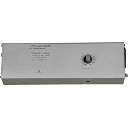
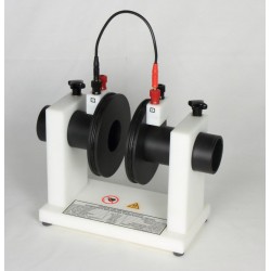
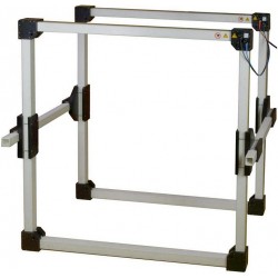
Schwarzbeck NFCN 9734 Compensation Network
New
- 85 kHz consists of a high current/ high voltage variable capacitor.
- Compensation capacitor reduces the total impedance of the series circuitry;
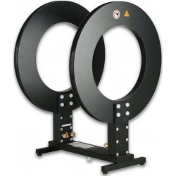
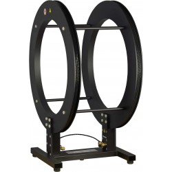
- Consisting of the Helmholtz coil HHS 5206-8 and the NFCN 9732 85 kHz at the operating frequency band of 80-90 kHz.
- It allows continuous currents of up to 15 Arms at generator voltages of less than 40 Vrms.
- Application: Immunity test induktive changing 85 kHz
PDF Downloads
Test Equipment Description
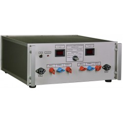
The primary function of the compensation network NFCN 9734 is to provide a serial compensation of the inductance of Helmholtz coils (e.g. the HHS 5206-16). Thus the currents needed to produce the desired field strength can be achieved using relatively low voltages.
An integrated shunt allows measuring the coilcurrent and serves as minimum load for the power amplifier.
The compensation network NFCN 9734 consists of a series circuit of a variable capacitor and a fuse. Its purpose is to compensate the inductance of the Helmholtz coils HHS 5206-16 at operating frequencies of about 200 Hz up to 200 kHz. If no compensation is necessary, the signal is looped through.
There are 23 different capacitors and a short available. They are connected between “Power Amplifier” and “Coil (to A)” utilizing relays.
The following graph shows the maximum reachable magnetic field strength of the system (HHS 5206-16, LFPA 9733 and NFCN 9734) – in relation to common standards.

Max. magnetic fieldstrength of HHS 5206-16 with LFPA 9733 and NFCN 9734
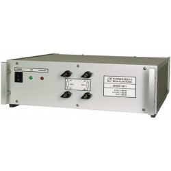
Internal 1 Ohm Shunt
The integrated 1 Ohm (800W) shunt allows measuring the coil-current and serves as minimum load for the power-amplifier. The internal fans are automatically enabled if the shunt becomes hot.
The shunt can be used stand-alone without the compensation network. But the cooling fans are only working when NFCN 9734 is turned on.
The following chart shows the total impedance of the shunt versus the frequency.
| Frequency, [kHz] | Impedance “1Ω”, [Ω] |
| 150 | 1.130 |
| 180 | 1.173 |
| 200 | 1.206 |
| 210 | 1.223 |
| 220 | 1.240 |
| 230 | 1.256 |
| 250 | 1.295 |
| 280 | 1.353 |

Hazard warning:
Attention: Life-endangering high voltages occur at the terminals of the coils and the NFCN 9734 during operation. If used in an inappropriate way this could lead to a life-threatening situation for the user!
Danger to life! High voltages!
The generator must be switched off every time wires are being connected or disconnected.
Important!
Switching capacitors is allowed without an applied signal level only. Otherwise the power amplifier could be damaged and the life expectancy of the relays will be decreased dramatically!
Currents between capacitors of different chargelevels can be extremely high. Occurring currents are limited by the loss resistance of the capacitors and the relay contacts only and can rise up to several hundreds of amperes. This can lead to welded relay contacts, especially at high capacitances within the lower frequency range.
Cooling
Please note that the air intake for cooling purposes is located on the sides of the amplifier and the warm air is exhausted at the back.
The amplifier must not be installed closer than 10 cm to a wall. It has to be installed in a way that the exhausted warm air cannot get into the housing again (thermal short). Pay attention to cooling especially when installing the amp into a 19” rack!
A 19’’-rack mount kit is available optionally.
19 other products in the same category:
-
Schwarzbeck NFCN 9731-100 Compensation Network
-
Schwarzbeck NFCN 9732 85 kHz Compensation Network
-
Schwarzbeck SHUNT 9571 High Power Shunt Resistor
-
Schwarzbeck HS 5136 Hall Sensor
-
Schwarzbeck HHS 5201-6 Circular Helmholtz Coils
-
Schwarzbeck HHS 5201-98 Circular Helmholtz Coils
-
Schwarzbeck HHS 5202-81 Circular Helmholtz Coils
-
Schwarzbeck HHS 5204-12 Circular Helmholtz Coils
-
Schwarzbeck HHS 5204-36 Circular Helmholtz Coils
-
Schwarzbeck HHS 5206-132 Circular Helmholtz Coils
-

Schwarzbeck HHS 5206-16 Circular Helmholtz Coils
-

Schwarzbeck HHS 5206-8 Circular Helmholtz Coils
-
Schwarzbeck HHS 5210 Helmholtz Coils
-
Schwarzbeck HHS 5210-100 Helmholtz Coils
-
Schwarzbeck HHS 5210-100-2.5 Helmholtz Coils
-
Schwarzbeck HHS 5213-100 Helmholtz Coils
-
Schwarzbeck HHS 5215-10 Helmholtz Coils
-
Schwarzbeck HHS 5215-100 Helmholtz Coils
-
Schwarzbeck HHS 5218 Helmholtz Coils