
No products
Product successfully added to your shopping cart
There are 0 items in your cart. There is 1 item in your cart.
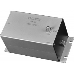
Schwarzbeck ISN T-Networks
- EMC Test Equipment
- Transient Generators
- RF Power Amplifiers
- DC - 300 kHz RF Amplifiers
- 10 kHz - 250 MHz RF Amplifiers
- 10 kHz - 400 MHz RF Amplifiers
- 10 kHz - 1 GHz RF Amplifiers
- 80 MHz - 1 GHz RF Amplifiers
- 1 GHz - 2 GHz RF Amplifiers
- 700 MHz - 4.2 GHz RF Amplifiers
- 1 GHz - 6 GHz RF Amplifiers
- 2 GHz - 8 GHz RF Amplifiers
- 6 GHz - 18 GHz RF Amplifiers
- 18 GHz - 40 GHz RF Amplifiers
- Pulse Amplifiers
- RF Field Strength Probes & Meters
- RF Conducted Immunity
- EMC Receivers/EMI Analyzers
- EMC Antennas
- Coupling Decoupling Networks (CDN's)
- Line Impedance Stabilization Networks (LISN's)
- RF Test Equipment
- EMC Probes
- EMC Measurement & Equipment Software
- Power Supplies
- Electrical Safety Analyzers
- High Precision Laboratory Power Analyzers & Meters
- Anechoic Chambers
- Over-the-Air (OTA) Test Chambers
- EMI RF Shielded Tent Enclosures
- RF Shielded Rooms
- EMC Absorber
- Positioning Equipment
- EMC/EMI Test Setup
- GTEM Cells / TEM Cells
- Reverberation Chambers
- Used RF Anechoic Chambers
- EMC Chamber Filters
- EMC Chamber Shielding Gaskets
- RF Shielded Doors
- Anechoic Chamber Accessories
- Fully Anechoic (FAR) Test Chambers
- Manufacturers
- 3ctest
- AE Techron
- AH Systems
- Amplifier Research
- Boonton
- Com-Power
- Diamond Engineering
- EM Test (Ametek CTS)
- EMC Partner
- EMC Test Design
- Empower High Power RF Amplifiers
- ETS-lindgren
- Log Periodic Dipole Array Antenna
- Near Field Probe Sets
- Double Ridge Horn Antennas
- Biconical Antennas
- Quad Ridge Horn Antennas
- Electric Field Probes
- GTEM's
- Positioners & Tripods
- Loop Antennas
- Biconilog Antennas
- LISN's (Line Impedance Stabilization Network)
- Shielded Enclosures/Rooms
- Monopole Antennas
- Field Generating Antennas
- Fischer Custom Communications
- Haefely Hipotronics
- Haefely EFT/Burst Immunity Test Systems
- Haefely Surge Combination Wave Test Systems
- Haefely Surge Damped Oscillating Wave Test Systems
- Haefely Electrostatic Discharge Test Systems (ESD)
- Haefely Surge Ring Wave Test Systems
- Haefely Surge Telecom Wave Test Systems
- Haefely Magnetic Field Test Systems
- Haefely CDN's (Coupling/Decoupling Networks)
- IFI Amplifiers
- Keysight (Agilent)
- MVG - Microwave Vision Group
- PMM / Narda
- Rohde & Schwarz RF Test Equipment
- Rohde & Schwarz Broadband RF Amplifiers
- Rohde & Schwarz Spectrum Analyzers
- Rohde & Schwarz Compliant EMI Test Receivers
- Rohde & Schwarz Isotropic RF Probes
- Rohde & Schwarz RF Signal Generators
- Rohde & Schwarz RF Switches
- Rohde & Schwarz Oscilloscopes
- Rohde & Schwarz RF Power Meters
- Rohde & Schwarz RF Power Sensors
- Schloder
- Schwarzbeck Mess-Elektronik
- Schwarzbeck Antennas
- Schwarzbeck Automotive Antennas
- Schwarzbeck Broadband Horn Antennas
- Schwarzbeck Biconical Antennas
- Schwarzbeck Logarithmic Periodic Broadband Antennas
- Schwarzbeck Stacked Log-Periodic Broadband Antennas
- Schwarzbeck Biconic Log-Periodic Antennas
- Schwarzbeck Dipole Antennas
- Schwarzbeck Rod Antennas
- Schwarbeck Antenna Baluns / Holders
- Schwarzbeck LISN Line Impedance Stabilisation Networks
- Schwarbeck Decoupling & Absorbing Clamps
- Schwarzbeck Field Probes
- Schwarzbeck Helmholtz Coils
- Schwarzbeck Antenna Masts
- Schwarzbeck Coupling/Decoupling Networks
- Schwarzbeck Antennas
- Solar Electronics
- Teseq (Schaffner)
- Teseq Automotive Transient Generators
- Teseq RF Test Equipment
- Teseq EFT/Burst Generators
- Teseq RF Immunity Generators
- Teseq ESD Guns
- Teseq Surge Generators
- Teseq Harmonics & Flicker Solutions
- Teseq Dips, Interrupts & Variations Equipment
- Teseq Ring Wave Generators
- Teseq Oscillatory Waves Generators
- Teseq Absorbing Clamps / Ferrite Tube
- Teseq EMC Antennas
- Teseq Current Probes
- Teseq Coupling Networks
- Thermo Keytek
- Vicreate
- Compliance Standards
- International (IEC/EN)
- EN/IEC 61000-3-2
- EN/IEC 61000-3-3
- IEC 61000-3-11
- IEC / EN 610000-3-12
- EN/IEC 61000-4-2
- EN/IEC 61000-4-3
- EN/IEC 61000-4-4
- EN/IEC 61000-4-5
- EN/IEC 61000-4-6
- EN/IEC 61000-4-7
- EN/IEC 61000-4-8
- EN/IEC 61000-4-9
- EN/IEC 61000-4-10
- EN/IEC 61000-4-11
- EN/IEC 61000-4-12
- EN/IEC 61000-4-16
- EN/IEC 61000-4-18
- EN/IEC 61000-4-19
- EN/IEC 61000-4-20
- EN/IEC 61000-4-21
- EN/IEC 61000-4-29
- EN/IEC 61000-4-31
- IEC 61000-4-39
- EN/IEC 62132
- SEMI F47 Voltage Sag Immunity
- Product Standards
- Military & Aerospace Standards
- Automotive EMC Standards
- CISPR Standards
- Telecom Testing
- ANSI/IEEE Standards
- FCC Part 15
- FCC Part 30
- International (IEC/EN)
- Application/Test Type
- Radiated Immunity
- Bulk Current Injection Testing
- RF Emissions Testing
- Conducted Immunity
- Conducted Emissions
- Antenna Pattern Measurement
- CE Mark Testing
- Intentional Radiator Testing
- Pulsed HIRF Radar
- Over-the-Air (OTA) Testing
- 5G Test Solutions
- Automotive EMC
- SAR Measurement Equipment
- Radiated Emissions
- Battery Simulator Test Equipment
- Services
- Clearance
Viewed products
-

Schwarzbeck SPLIT 100...
DC ... 30 MHz Frequency Range Is a...
 View larger
Schwarzbeck SPLIT 100 Symmetrical Splitter
New
- DC ... 30 MHz Frequency Range
- Is a resistive, symmetrical two port splitter
- With an impedance of 100 Ω
- It is part of the measurement setup according to EN 50561-1
PDF Downloads
Test Equipment Description
The Schwarzbeck SPLIT 100 is a resistive, symmetrical two port splitter with an impedance of 100 Ω.
It is part of the measurement setup according to EN 50561-1 which is explained in chapter 9.2. Figure 1 shows the measurement setup with the available components.
The symmetrical splitter SPLIT 100 belongs to a series of measurement equipment for measuring power line communication devices.
This splitter is built in a resistive way. Resistors made with tight tolerances and temperature stable have been used. Thus the device can be used for a wide frequency range.
The SPLIT 100 has a very flat frequency response of typically less than 0.2 dB and can be used up to above 50 MHz. The input and output connectors are symmetrical to earth and show identical properties in each of the three directions.
Splitters like this do have an insertion loss of 6 dB as a matter of principle. They are being used as power dividers (signal distributors) or combiners (to merge signals) also. A 4 dB attenuator is built in at port 3 which results in an attenuation of exactly 10 dB.
This port has to be connected to the switchable, symmetrical attenuator “SYMAT 40”. The total attenuation between AE and EuT results from the sum of the set attenuation of the SYMAT 40 plus the 10 dB insertion loss from port 3 of the SPLIT 100.
If a measurement has to be performed at 20 dB decoupling between AE and EuT for instance, the switch at the SYMAT 40 has to be set to 10 dB.
Safety note
The SPLIT 100 may not be used at the mains directly. Local safety rules for devices connected to mains have to be followed.
| Specifications | |
| Frequency range | DC ... 30 MHz |
| Usable frequency range | DC … >50 MHz |
| Insertion loss Port1, Port2 | 6 dB ±0.2 dB |
| Port3 | 10 dB ±0.2 dB |
| Frequency response | <+/-0.5 dB |
| Nominal Impedance | 100 Ω |
| Max. Input power | 1 W |
| VSWR | < 1.1 : 1 @ 30 MHz |
| Proof voltage against housing | >500 VDC |
| Housing material | Aluminium |
| Housing dimensions | 125 x 104 x 50 mm |
| Weight | ca. 270 g |
| Terminals | 4 mm Safety Laboratory Jack |
| Terminal spacing | 19 mm |
| Ground connectors | Bottom of case and 4 mm laboratory jack |

Fig. 1: Test equipment arrangement, EN-50561-1, Fig. 4

Fig. 1: Typical Transmission between Ports 1 and 2, port 3 terminated with 100 Ω
7 other products in the same category:
-
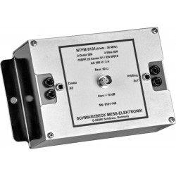
Schwarzbeck NTFM 8131 2-Wire Impedance Stabilisation Network, 9 kHz - 30 MHz
-
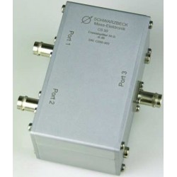
Schwarzbeck CS-50 Unsymmetrical Splitter
-
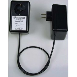
Schwarzbeck CU 50561-1 Coupling Unit
-
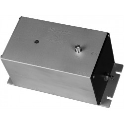
Schwarzbeck ISN S1 Impedance Stabilisation Network
-
Schwarzbeck ISN S8 Impedance Stabilisation Network
-
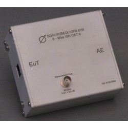
Schwarzbeck NTFM 8158 8-Wire Impedance Stabilization Network
-
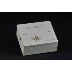
Schwarzbeck CAT5 8158 8-Wire Impedance Stabilization Network