
No products
Product successfully added to your shopping cart
There are 0 items in your cart. There is 1 item in your cart.
Impedance Stabilization Networks (ISN's)
- EMC Test Equipment
- Transient Generators
- RF Power Amplifiers
- DC - 300 kHz RF Amplifiers
- 10 kHz - 250 MHz RF Amplifiers
- 10 kHz - 400 MHz RF Amplifiers
- 10 kHz - 1 GHz RF Amplifiers
- 80 MHz - 1 GHz RF Amplifiers
- 1 GHz - 2 GHz RF Amplifiers
- 700 MHz - 4.2 GHz RF Amplifiers
- 1 GHz - 6 GHz RF Amplifiers
- 2 GHz - 8 GHz RF Amplifiers
- 6 GHz - 18 GHz RF Amplifiers
- 18 GHz - 40 GHz RF Amplifiers
- Pulse Amplifiers
- RF Field Strength Probes & Meters
- RF Conducted Immunity
- EMC Receivers/EMI Analyzers
- EMC Antennas
- Coupling Decoupling Networks (CDN's)
- Line Impedance Stabilization Networks (LISN's)
- RF Test Equipment
- EMC Probes
- EMC Measurement & Equipment Software
- Power Supplies
- Electrical Safety Analyzers
- High Precision Laboratory Power Analyzers & Meters
- Anechoic Chambers
- Over-the-Air (OTA) Test Chambers
- EMI RF Shielded Tent Enclosures
- RF Shielded Rooms
- EMC Absorber
- Positioning Equipment
- EMC/EMI Test Setup
- GTEM Cells / TEM Cells
- Reverberation Chambers
- Used RF Anechoic Chambers
- EMC Chamber Filters
- EMC Chamber Shielding Gaskets
- RF Shielded Doors
- Anechoic Chamber Accessories
- Fully Anechoic (FAR) Test Chambers
- Manufacturers
- 3ctest
- AE Techron
- AH Systems
- Amplifier Research
- Boonton
- Com-Power
- Diamond Engineering
- EM Test (Ametek CTS)
- EMC Partner
- EMC Test Design
- Empower High Power RF Amplifiers
- ETS-lindgren
- Log Periodic Dipole Array Antenna
- Near Field Probe Sets
- Double Ridge Horn Antennas
- Biconical Antennas
- Quad Ridge Horn Antennas
- Electric Field Probes
- GTEM's
- Positioners & Tripods
- Loop Antennas
- Biconilog Antennas
- LISN's (Line Impedance Stabilization Network)
- Shielded Enclosures/Rooms
- Monopole Antennas
- Field Generating Antennas
- Fischer Custom Communications
- Haefely Hipotronics
- Haefely EFT/Burst Immunity Test Systems
- Haefely Surge Combination Wave Test Systems
- Haefely Surge Damped Oscillating Wave Test Systems
- Haefely Electrostatic Discharge Test Systems (ESD)
- Haefely Surge Ring Wave Test Systems
- Haefely Surge Telecom Wave Test Systems
- Haefely Magnetic Field Test Systems
- Haefely CDN's (Coupling/Decoupling Networks)
- IFI Amplifiers
- Keysight (Agilent)
- MVG - Microwave Vision Group
- PMM / Narda
- Rohde & Schwarz RF Test Equipment
- Rohde & Schwarz Broadband RF Amplifiers
- Rohde & Schwarz Spectrum Analyzers
- Rohde & Schwarz Compliant EMI Test Receivers
- Rohde & Schwarz Isotropic RF Probes
- Rohde & Schwarz RF Signal Generators
- Rohde & Schwarz RF Switches
- Rohde & Schwarz Oscilloscopes
- Rohde & Schwarz RF Power Meters
- Rohde & Schwarz RF Power Sensors
- Schloder
- Schwarzbeck Mess-Elektronik
- Schwarzbeck Antennas
- Schwarzbeck Automotive Antennas
- Schwarzbeck Broadband Horn Antennas
- Schwarzbeck Biconical Antennas
- Schwarzbeck Logarithmic Periodic Broadband Antennas
- Schwarzbeck Stacked Log-Periodic Broadband Antennas
- Schwarzbeck Biconic Log-Periodic Antennas
- Schwarzbeck Dipole Antennas
- Schwarzbeck Rod Antennas
- Schwarbeck Antenna Baluns / Holders
- Schwarzbeck LISN Line Impedance Stabilisation Networks
- Schwarbeck Decoupling & Absorbing Clamps
- Schwarzbeck Field Probes
- Schwarzbeck Helmholtz Coils
- Schwarzbeck Antenna Masts
- Schwarzbeck Coupling/Decoupling Networks
- Schwarzbeck Antennas
- Solar Electronics
- Teseq (Schaffner)
- Teseq Automotive Transient Generators
- Teseq RF Test Equipment
- Teseq EFT/Burst Generators
- Teseq RF Immunity Generators
- Teseq ESD Guns
- Teseq Surge Generators
- Teseq Harmonics & Flicker Solutions
- Teseq Dips, Interrupts & Variations Equipment
- Teseq Ring Wave Generators
- Teseq Oscillatory Waves Generators
- Teseq Absorbing Clamps / Ferrite Tube
- Teseq EMC Antennas
- Teseq Current Probes
- Teseq Coupling Networks
- Thermo Keytek
- Vicreate
- Compliance Standards
- International (IEC/EN)
- EN/IEC 61000-3-2
- EN/IEC 61000-3-3
- IEC 61000-3-11
- IEC / EN 610000-3-12
- EN/IEC 61000-4-2
- EN/IEC 61000-4-3
- EN/IEC 61000-4-4
- EN/IEC 61000-4-5
- EN/IEC 61000-4-6
- EN/IEC 61000-4-7
- EN/IEC 61000-4-8
- EN/IEC 61000-4-9
- EN/IEC 61000-4-10
- EN/IEC 61000-4-11
- EN/IEC 61000-4-12
- EN/IEC 61000-4-16
- EN/IEC 61000-4-18
- EN/IEC 61000-4-19
- EN/IEC 61000-4-20
- EN/IEC 61000-4-21
- EN/IEC 61000-4-29
- EN/IEC 61000-4-31
- IEC 61000-4-39
- EN/IEC 62132
- SEMI F47 Voltage Sag Immunity
- Product Standards
- Military & Aerospace Standards
- Automotive EMC Standards
- CISPR Standards
- Telecom Testing
- ANSI/IEEE Standards
- FCC Part 15
- FCC Part 30
- International (IEC/EN)
- Application/Test Type
- Radiated Immunity
- Bulk Current Injection Testing
- RF Emissions Testing
- Conducted Immunity
- Conducted Emissions
- Antenna Pattern Measurement
- CE Mark Testing
- Intentional Radiator Testing
- Pulsed HIRF Radar
- Over-the-Air (OTA) Testing
- 5G Test Solutions
- Automotive EMC
- SAR Measurement Equipment
- Radiated Emissions
- Battery Simulator Test Equipment
- Services
- Clearance
Viewed products
-

Schwarzbeck ISN S8...
150 kHz – 230 MHz Frequency Range ISN...
 View larger
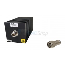
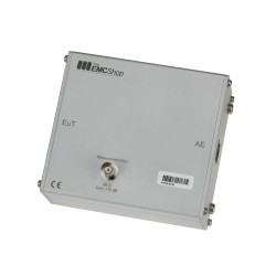
Schwarzbeck ISN S8 Impedance Stabilisation Network
New
- 150 kHz – 230 MHz Frequency Range
- ISN acc. CISPR 22 Ed.5.5:2006, Annex D, D9 for coaxial lines
- Can be used to measure the conducted voltage emissions of telecommunication and data processing equipment
- It is designed to measure coaxial line. It is based on IEC/CISPR 22 and the related national standards
- Provide sufficient decoupling from the equipment under test (EuT) to the auxiliary equipment (AE)
PDF Downloads
Test Equipment Description
The ISN S8 can be used to measure the conducted voltage emissions of telecommunication and data processing equipment. It is designed to measure shielded cables with up to 4 wire pairs. It is based on IEC/CISPR 22 and the related national standards. The special circuitry and design is described in CISPR 22, CISPR 32 Annex G.11 and EN 55022 Annex D figure D.11 respectively. The ISN must provide sufficient decoupling from the equipment under test (EuT) to the auxiliary equipment (AE) which could be a communication device or a kind of load. The measured conducted voltage is coupled out to the BNC connector on top of the ISN S8. An EMI receiver or spectrum analyzer is most commonly used for a measuring instrument.
The ISN S8 can also be used in the other direction to inject conducted radio frequency disturbance into the shield of communication wires. This method is described in IEC/EN 61000-4-6. If the ISN S8 is used for injection it is also referred to as coupling decoupling network (CDN).
The ISN S8 is capable to provide 1000 MBit/s (Gigabit-Ethernet, 1000BASE-T). A cable of the suitable cable category is built in and is wired according to TIA-568A/B.
Application
The measurement is described in detail in CISPR 22, CISPR 32 and EN 55022.
The equipment under test must be connected to the EuT-port. The auxiliary equipment has to be connected to the AEport. The EMI-receiver or spectrum analyser has to be connected to the BNC port of the ISN S8 using a coaxial line.
Fixture lugs at the bottom plate of the ISN S8 allow to fix the device with screws to the cabin wall if wished.
As CISPR 22 defines the limits for conducted emissions in a 150 Ω system there is an 100 Ω resistor in series to the BNC connector. In combination with the 50 Ω input resistance of the measurement device a voltage division factor of 1:3 follows. In a logarithmic scale this is equal to 9.5 dB. The measured voltages across 50 Ω therefore has to be multiplied with 3 or in other words a correction of 9.5 dB must be added. This value of 9.5 dB is called the voltage division factor (VDF). This VDF is slightly frequency dependent. For very precise measurements it is recommended to take the exact frequency dependent VDF into account (see calibration certificate).
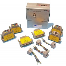
The shield or outer cable is defined as the common mode point for the EuT connector of ISN/CDN equipment. To be able to do a measurement (i.e. the impedance of the ISN or to normalize the voltage division factor) at this measuring point an adapter is needed.
This adapter can be purchased separately and is needed to connect the shield of the RJ45 socket to the measurement device. It is called “CA ISN S8” where the Usection can be attached to the shield of the RJ45 socket at the EuT part of the ISN and the 4 mm plug matches into the 50 Ω to 150 Ω adapter SR100-6W which can be purchased separately as well. It is given that when putting the ISN S8 and the SR100-6W together the normative distance of 30 mm between the front surfaces automatically is fulfilled.
 To enable you to connect your own measurement equipment the CA ISN S8 consists of two parts and can be taken apart very easily. A 4 mm plug provides the connection to the SR100-6W keeping the given distance.
If you want to use the ISN S8 as a CDN the use of the adapter “CA ISN S8”and the 50 Ω to 150 Ω adapter “SR100-6W” is mandatory. The measurement setup is described within the norm IEC/EN 61000- 4-6 picture 8c.
ISN Voltage Division Factor

ISN Impedance (Magnitude)

| Specifications | |
| Frequency Range | 150 kHz – 230 MHz |
| Type of cable | 4 x STP (shielded twisted pair) 100 Ω impedance |
| Connector | RJ45 |
| Max. voltage line – ground | 150 V DC 100 V AC |
| Max. line current/path | 1 A DC |
| Common mode impedance EuTside: 150 kHz – 30 MHz 30 MHz – 230 MHz | 150 Ω ±20 Ω 150 Ω + 60 Ω/-45 Ω |
| Phase error | 0° ±20° |
| Measuring port | 50 Ω BNC |
| Max. voltage measuring port | <20 V AC |
| Voltage divisions factor EuT – measuring port: 150 kHz – 30 MHz 30 MHz – 230 MHz | 9.5 dB ±1 dB 9.5 dB +4 dB/-2 dB |
| 3 dB transmission bandwith EuT – AE | >250 MHz |
| Cable-/RJ-45 connector cat. | CAT 6 |
| Dimensions W x H x D | 225 mm x 129 mm x 105 mm |
| Weight | ~1265 g |
| Acc. to standard | CISPR 22 CISPR 32 EN 55022 |
Associated EMC Test Equipment

29 other products in the same category:
-
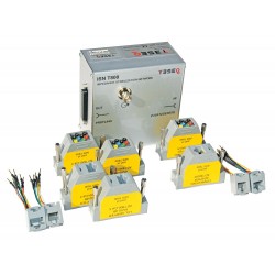
Teseq ISN T800S Impedance Stabilization Network per CISPR 22/32 Figure D.3/G.3
-

Rent Com-Power ISN-T8 for One, Two, Four, Unshielded Balanced Pair, CAT-3, CAT-5
-
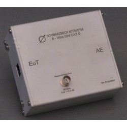
Schwarzbeck NTFM 8158 8-Wire Impedance Stabilization Network
-
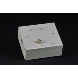
Schwarzbeck CAT5 8158 8-Wire Impedance Stabilization Network
-
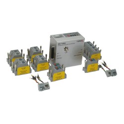
Teseq ISN T8 Impedance Stabilization Network (ISN) for Unscreened Balanced Pairs
-
Teseq ISN T4A Impedance Stabilization Network (ISN) for Unscreened Balanced Pairs
-

Com-Power ISN-T8 Impedance Stabilization Network 150 kHz to 30 MHz
-
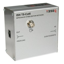
Teseq ISN T8-Cat6 Impedance Stabilization Network (ISN) for Unscreened Balanced Pairs
-
FCC CISPR 22 Impedance Stabilization Network (ISN) FCC-TLISN-T4-02
-
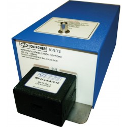
Com-Power ISN-T2 Impendace Stabilization Network 150 kHz to 30 MHz
-
Teseq ISN PLT Impedance Stabilization Network (ISN) for Power Line Telecommunication (PLT)
-
Teseq ISN ST08C Impedance Stabilization Network for Shielded Balanced Pairs
-

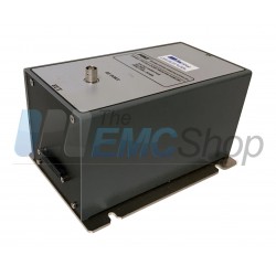
Teseq ISN S752 Impedance Stabilization Network for Coaxial Lines
-

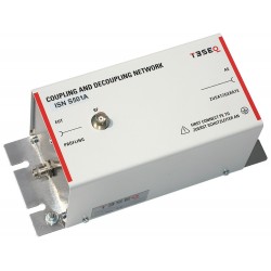
Teseq ISN S501A Impedance Stabilization Network for Coaxial Lines
-
Teseq ISN S751 Impedance Stabilization Network for Coaxial Lines
-
Teseq ISN S502A Impedance Stabilization Network for Coaxial Lines
-
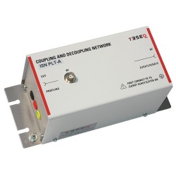
Teseq ISN PLT-A Impedance Stabilization Network (ISN) for Power Line Telecommunication (PLT)
-

Newtons4th (N4L) IMP163 Impedance Network for Harmonics & Flicker, Three Phase, 16 A
-

Newtons4th (N4L) IMP753 Impedance Network for Harmonics & Flicker, Three Phase, 75 A
-
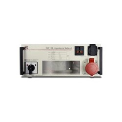
Newtons4th (N4L) IMP323 Impedance Network for Harmonics & Flicker, Three Phase, 32 A
-

Newtons4th (N4L) IMP161 Impedance Network for Harmonics & Flicker, Single Phase, 16 A
-

Rent Teseq ISN T8 Impedance Stabilization Network (ISN) for Unscreened Balanced Pairs
-
Com-Power ISN-T8 Impendace Stabilization Network and Calibration Kit
-
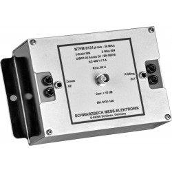
Schwarzbeck NTFM 8131 2-Wire Impedance Stabilisation Network, 9 kHz - 30 MHz
-
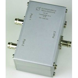
Schwarzbeck CS-50 Unsymmetrical Splitter
-
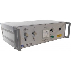
Chase MN2050B Line Impedance Stabilization Network (LISN)
-
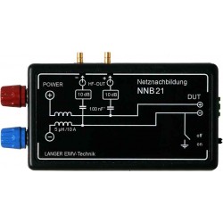
Langer EMV-Technik NNB 21 Line Impedance Stabilisation Network
-
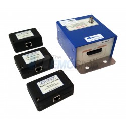
ISN30M Impedance Stabilization Network (ISN) with Coupling/Decoupling Network (CDN)
-
LISN-CISPR16-32A Line Impedance Stabilization Network