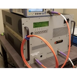
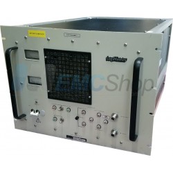
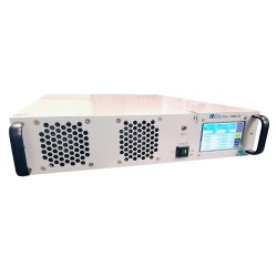
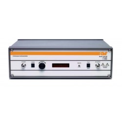
No products
Product successfully added to your shopping cart
There are 0 items in your cart. There is 1 item in your cart.
2 GHz - 8 GHz RF Amplifiers
- EMC Test Equipment
- Transient Generators
- RF Power Amplifiers
- DC - 300 kHz RF Amplifiers
- 10 kHz - 250 MHz RF Amplifiers
- 10 kHz - 400 MHz RF Amplifiers
- 10 kHz - 1 GHz RF Amplifiers
- 80 MHz - 1 GHz RF Amplifiers
- 1 GHz - 2 GHz RF Amplifiers
- 700 MHz - 4.2 GHz RF Amplifiers
- 1 GHz - 6 GHz RF Amplifiers
- 2 GHz - 8 GHz RF Amplifiers
- 6 GHz - 18 GHz RF Amplifiers
- 18 GHz - 40 GHz RF Amplifiers
- Pulse Amplifiers
- RF Field Strength Probes & Meters
- RF Conducted Immunity
- EMC Receivers/EMI Analyzers
- EMC Antennas
- Coupling Decoupling Networks (CDN's)
- Line Impedance Stabilization Networks (LISN's)
- RF Test Equipment
- EMC Probes
- EMC Measurement & Equipment Software
- Power Supplies
- Electrical Safety Analyzers
- High Precision Laboratory Power Analyzers & Meters
- Anechoic Chambers
- Over-the-Air (OTA) Test Chambers
- EMI RF Shielded Tent Enclosures
- RF Shielded Rooms
- EMC Absorber
- Positioning Equipment
- EMC/EMI Test Setup
- GTEM Cells / TEM Cells
- Reverberation Chambers
- Used RF Anechoic Chambers
- EMC Chamber Filters
- EMC Chamber Shielding Gaskets
- RF Shielded Doors
- Anechoic Chamber Accessories
- Fully Anechoic (FAR) Test Chambers
- Manufacturers
- 3ctest
- AE Techron
- AH Systems
- Amplifier Research
- Boonton
- Com-Power
- Diamond Engineering
- EM Test (Ametek CTS)
- EMC Partner
- EMC Test Design
- Empower High Power RF Amplifiers
- ETS-lindgren
- Log Periodic Dipole Array Antenna
- Near Field Probe Sets
- Double Ridge Horn Antennas
- Biconical Antennas
- Quad Ridge Horn Antennas
- Electric Field Probes
- GTEM's
- Positioners & Tripods
- Loop Antennas
- Biconilog Antennas
- LISN's (Line Impedance Stabilization Network)
- Shielded Enclosures/Rooms
- Monopole Antennas
- Field Generating Antennas
- Fischer Custom Communications
- Haefely Hipotronics
- Haefely EFT/Burst Immunity Test Systems
- Haefely Surge Combination Wave Test Systems
- Haefely Surge Damped Oscillating Wave Test Systems
- Haefely Electrostatic Discharge Test Systems (ESD)
- Haefely Surge Ring Wave Test Systems
- Haefely Surge Telecom Wave Test Systems
- Haefely Magnetic Field Test Systems
- Haefely CDN's (Coupling/Decoupling Networks)
- IFI Amplifiers
- Keysight (Agilent)
- MVG - Microwave Vision Group
- PMM / Narda
- Rohde & Schwarz RF Test Equipment
- Rohde & Schwarz Broadband RF Amplifiers
- Rohde & Schwarz Spectrum Analyzers
- Rohde & Schwarz Compliant EMI Test Receivers
- Rohde & Schwarz Isotropic RF Probes
- Rohde & Schwarz RF Signal Generators
- Rohde & Schwarz RF Switches
- Rohde & Schwarz Oscilloscopes
- Rohde & Schwarz RF Power Meters
- Rohde & Schwarz RF Power Sensors
- Schloder
- Schwarzbeck Mess-Elektronik
- Schwarzbeck Antennas
- Schwarzbeck Automotive Antennas
- Schwarzbeck Broadband Horn Antennas
- Schwarzbeck Biconical Antennas
- Schwarzbeck Logarithmic Periodic Broadband Antennas
- Schwarzbeck Stacked Log-Periodic Broadband Antennas
- Schwarzbeck Biconic Log-Periodic Antennas
- Schwarzbeck Dipole Antennas
- Schwarzbeck Rod Antennas
- Schwarbeck Antenna Baluns / Holders
- Schwarzbeck LISN Line Impedance Stabilisation Networks
- Schwarbeck Decoupling & Absorbing Clamps
- Schwarzbeck Field Probes
- Schwarzbeck Helmholtz Coils
- Schwarzbeck Antenna Masts
- Schwarzbeck Coupling/Decoupling Networks
- Schwarzbeck Antennas
- Solar Electronics
- Teseq (Schaffner)
- Teseq Automotive Transient Generators
- Teseq RF Test Equipment
- Teseq EFT/Burst Generators
- Teseq RF Immunity Generators
- Teseq ESD Guns
- Teseq Surge Generators
- Teseq Harmonics & Flicker Solutions
- Teseq Dips, Interrupts & Variations Equipment
- Teseq Ring Wave Generators
- Teseq Oscillatory Waves Generators
- Teseq Absorbing Clamps / Ferrite Tube
- Teseq EMC Antennas
- Teseq Current Probes
- Teseq Coupling Networks
- Thermo Keytek
- Vicreate
- Compliance Standards
- International (IEC/EN)
- EN/IEC 61000-3-2
- EN/IEC 61000-3-3
- IEC 61000-3-11
- IEC / EN 610000-3-12
- EN/IEC 61000-4-2
- EN/IEC 61000-4-3
- EN/IEC 61000-4-4
- EN/IEC 61000-4-5
- EN/IEC 61000-4-6
- EN/IEC 61000-4-7
- EN/IEC 61000-4-8
- EN/IEC 61000-4-9
- EN/IEC 61000-4-10
- EN/IEC 61000-4-11
- EN/IEC 61000-4-12
- EN/IEC 61000-4-16
- EN/IEC 61000-4-18
- EN/IEC 61000-4-19
- EN/IEC 61000-4-20
- EN/IEC 61000-4-21
- EN/IEC 61000-4-29
- EN/IEC 61000-4-31
- IEC 61000-4-39
- EN/IEC 62132
- SEMI F47 Voltage Sag Immunity
- Product Standards
- Military & Aerospace Standards
- Automotive EMC Standards
- CISPR Standards
- Telecom Testing
- ANSI/IEEE Standards
- FCC Part 15
- FCC Part 30
- International (IEC/EN)
- Application/Test Type
- Radiated Immunity
- Bulk Current Injection Testing
- RF Emissions Testing
- Conducted Immunity
- Conducted Emissions
- Antenna Pattern Measurement
- CE Mark Testing
- Intentional Radiator Testing
- Pulsed HIRF Radar
- Over-the-Air (OTA) Testing
- 5G Test Solutions
- Automotive EMC
- SAR Measurement Equipment
- Radiated Emissions
- Battery Simulator Test Equipment
- Services
- Clearance
Viewed products
-

Amplifier Research...
Rental Rate is Monthly Rentals Ship...
-

Schwarzbeck NNHV...
High Voltage LISN acc. to CISPR 25...
 View larger
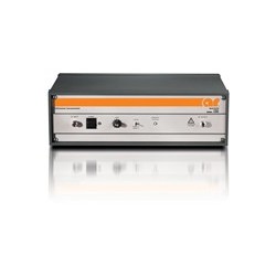
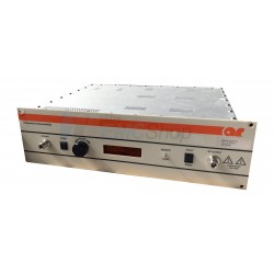
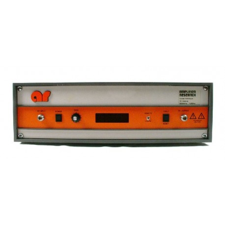
 Amplifier Research 10S1G4 RF Amplifier, 700 MHz - 4.2 GHz, 10 Watts
Used
- Rental Rate is Monthly
- Rentals Ship Immediately
- Purchase Used RF Amplifiers
- Fresh Output Curve Provided
- Output: 10 Watts Continuous P1dB
- Frequency Range: 700 MHz - 4.2 GHz
- AC Input: 120VAC
- Connectors:
- RF In: N(f)-type
- RF Out: N(f)-type
Typically in Stock
PDF Downloads
Specifications
| Frequency Range | 0.7–4.2GHz instantaneously |
| Standards Met | CE Mark Testing |
| RF Connector | RF Connector Type N female REMOTE INTERFACES: IEEE-488-24 pin female RS-232-9 pin Subminiature D (female) RS-232 (fiber optic)-Type ST USB 2.0-Type B Ethernet-RJ-45 |
| Gain | (at maximum setting) 43 dB minimum (Continuous Range) 10 dB minimum |
| RF Input Voltage | 1.0 milliwatt maximum for rated output |
| Impedance | 50 ohms, VSWR 2.0:1 maximum |
| Input | 90-132, 180-264 VAC 50/60 Hz, single phase 210 watts maximum |
| Output | POWER OUTPUT @ 3dB COMPRESSION Nominal 25 watts Minimum 20 watts POWER OUTPUT @ 1dB COMPRESSION Nominal 22 watts Minimum 18 watts |
| Flatness | ± 1.5 dB |
| Harmonic Distortion (THD) | Minus 20 dBc maximum at 15 watts |
| Dimensions | 19.8 x 6.1 x 14.8 in |
| Weight | 37 lbs |
Test Equipment Description
How to Rent the Amplifier Research 10S1G4:
- Click "Add to Cart" above
- Register or Check Out as a Guest
- Select Shipping Method (use "My Account" and input your account # and method)
- Order Confirmation and Tracking Info Follows
The Amplifier Research 10S1G4 RF Amplifier, 700 MHz - 4.2 GHz, 10 Watts is a solid state, self-contained, air-cooled, broadband amplifier designed for applications where instantaneous bandwidth and high gain are required.
The 10S1G4, when used with a sweep generator, will provide a minimum of 10 watts of RF power.
Included is a front panel gain control which permits the operator to conveniently set the desired output level. The AR 20S1G4 is protected from RF input overdrive by an RF input leveling circuit which controls the RF input level to the RF amplifier first stage when the RF input level is increased above 0 dBm.
The RF amplifier stages are protected from over-temperature by removing the DC voltage to them if an over temperature condition occurs due to cooling blockage or fan failure. There is a digital display on the front panel to indicate the operate status and fault conditions when an over-temperature or power supply fault has occurred. The unit can be returned to operate when the condition has been cleared. The AR 10S1G4 includes digital control for both local and remote control of the amplifier. All amplifier control functions and status indications are available remotely in GPIB/IEEE- 488 format, RS-232 hardwire and fiber optic, USB, and Ethernet. The bus interface connector is located on the back panel and positive control of local or remote operation is assured by a Local/Remote switch on the front panel of the amplifier.


