Conducted Susceptibility

The EMC can provide test eqipment for subcategories of MIL-STD-461; Conducted Susceptibility with applications for:

Power Leads, Antenna Port, Intermodulation, Rejection of Undesired Signals, Cross-Modulation, Structure Current, Bulk Cable Injection, Impulse Excitation, Damped Sinusoidal Transients, Cables and Power Leads, Lightning Induced Transients, and Personnel Borne Electrostatic Discharge

Get Application Support, Pricing, Lead Time and More: Contact Form

Conducted Susceptibility There are 43 products.

Subcategories

  • MIL-STD-461 CS101


    MIL-STD-461 Testing Services         Radiated Immunity & Susceptibility        Antenna Testing            Emissions Testing


    Get Application Support, Pricing, Lead Time and More: Contact Form

    MIL-STD-461 CS101 Purpose

    Conducted Susceptibility, Power Leads, 30 Hz to 150 kHz

    This test procedure is used to verify the ability of the EUT to withstand signals coupled onto input power leads. There are two methods provided for making measurements of the applied signal. The first uses an oscilloscope with a power input isolation transformer. The second uses a measurement receiver together with a transducer. The transducer is intended to electrically isolate the receiver from the EUT power and reduce the signal levels to protect the receiver.

    MIL-STD-461 CS101 Test Equipment

    The test equipment shall be as follows:

    a. Signal generator

    b. Power amplifier

    c. Oscilloscope or measurement receiver

    d. Coupling transformer

    e. Capacitor, 10 μF

    f. Isolation transformer

    g. Resistor, 0.5 ohm

    h. LISNs

    i. Transducer for measurement receiver use


    MIL-STD-461 CS101 Test Setup

    MIL-STD-461 CS101 Test Setup

  • MIL-STD-461 CS109

    CS109 Purpose

    MIL-STD-461 CS109 Conducted Susceptibility, Structure Current, 60 Hz to 100 kHz

    This test procedure is used to verify the ability of the EUT to withstand structure currents.

    Test Equipment

    The test equipment shall be as follows:

    a. Signal generator

    b. Amplifier (if required)

    c. Isolation transformers

    d. Current probe

    e. Measurement receiver

    f. Resistor, 0.5 ohm

    g. Coupling transformer

    Get Application Support, Pricing, Lead Time and More: Contact Form

  • MIL-STD-461 CS114

    CS114 Purpose

    Conducted Susceptibility, Bulk Cable Injection (BCI)

    The MIL-STD-461 CS114 requirement is applicable from 10 kHz to 200 MHz for all interconnecting cables, including power cables.

    The MIL-STD-461 CS114 test procedure is used to verify the ability of the EUT to withstand RF signals coupled onto EUT associated cabling.

    Test Equipment

    The test equipment shall be as follows:

    a. Measurement receivers

    b. Current injection probes (maximum and minimum insertion loss shown on Figure CS114-2)

    c. Current probes

    d. Calibration fixture: coaxial transmission line with 50 ohm characteristic impedance, coaxial connections on both ends, and space for an injection probe around the center conductor.

    e. Directional couplers

    f. Signal generators

    g. Plotter h. Attenuators, 50 ohm

    i. Coaxial loads, 50 ohm

    j. Power amplifiers

    k. LISN

    The EMC Shop offers turn key solutions to complete conductred susceptibility tests required per MIL-STD-461 CS114.

    Get Application Support, Pricing, Lead Time and More: Contact Form

  • MIL-STD-461 CS115

    CS115 Purpose

    Conducted Susceptibility, bulk cable injection, impulse excitation

    This test procedure is used to verify the ability of the EUT to withstand impulse signals coupled onto EUT associated cabling.

    Test Equipment

    The test equipment shall be as follows:

    a. Pulse generator, 50 ohm, charged line (coaxial)
    b. Current injection probe
    c. Drive cable, 50 ohm, 2 meters, 0.5 dB or less insertion loss at 500 MHz
    d. Current probe
    e. Calibration fixture: coaxial transmiss
    ion line with 50 ohm characteristic impedance,
    coaxial connections on both ends, and space for an injection probe around the center
    conductor.
    f. Oscilloscope, 50 ohm input impedance
    g. Attenuators, 50 ohm
    h. Coaxial loads, 50 ohm
    i. LISNs

    Get Application Support, Pricing, Lead Time and More: Contact Form

  • MIL-STD-461 CS116

    CS116 Purpose

    Conducted susceptibility, damped sinusoidal transients, cables and power leads.

    This requirement is applicable from 10 kHz to 100 MHz for all interconnecting cables, including power cables, and individual high side power leads. Power returns and neutrals need not be tested individually.
    This test procedure is used to verify the ability of the EUT to withstand damped sinusoidal transients coupled onto EUT associated cables and power leads.

    Test Equipment

    The test equipment shall be as follows:

    a. Damped sinusoid transient generator, ≤ 100 ohm output impedance
    b. Current injection probe
    c. Oscilloscope, 50 ohm input impedance
    d. Calibration fixture: Coaxial transmission line with 50 ohm characteristic impedance, coaxial connections on both ends, and space for an injection probe around the center conductor
    e. Current probes
    f. Waveform recording device
    g. Attenuators, 50 ohm
    h. Measurement receivers
    i. Coaxial loads, 50 ohm
    j. LISNs

    Get Application Support, Pricing, Lead Time and More: Contact Form

  • MIL-STD-461 CS117

    CS117 Purpose

    Conducted susceptibility, lightning induced transients, cables and power leads.

    Military Standard 461 Version G's new section CS 117 requires multiple stroke surge testing using a lightning transient generator. This requirement is similar to the well established RTCA/DO-160 Section 22 lightning immunity test standard.
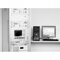
    Test Equipment

    The test equipment shall be as follows:

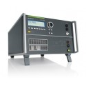
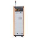
    a. Lightning transient generator

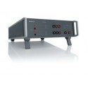
    b. Injection Transformers

    c. Oscilloscope

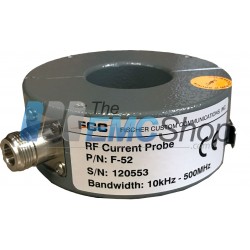
    d. Current monitor probes

    e. Attenuators, 50 ohm, as needed on current monitor probes

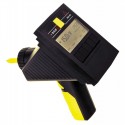
    f. Voltage monitor probes, high impedance

    g. Monitor loop, low impedance wire loop

    h. Calibration loop, low impedance wire loop

    i. Capacitor, >28,000 µF for DC power inputs
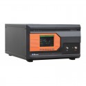
    j. LISN

    Get Application Support, Pricing, Lead Time and More: Contact Form

  • MIL-STD-461 CS118

    CS118 Purpose

    Personnel Borne Electrostatic Discharge

    This requirement is applicable to electrical, electronic, and electromechanical subsystems and equipment that have a man-machine interface. It is not applicable to ordnance items.

    Test Equipment

    The test equipment shall be as follows:

    a. ESD Generator, adjustable from ±2kV to ±15kV (minimum range),
    and Table X for simplified ESD generator characteristics.
    b. ESD network, 150 picofarads (pF) capacitance, 330 ohm discharge resistance.
    c. Contact discharge tip Figure CS118-2.
    d. Air discharge tip Figure CS118-2.
    e. Electrostatic voltmeter.
    f. Oscilloscope, single event bandwidth ≥ 1 GHz.
    g. ESD current target, input resistance 2 ±5% ohms, Figure CS118-3.
    h. Attenuator, 20 dB.
    i. Coaxial cable, 50 ohm impedance, ≤ 1 meter.
    j. Metallic ground plane.
    k. Ionizer or one (1) megohm resistor (1MΩ±10%).

    Get Application Support, Pricing, Lead Time and More: Contact Form

per page
Showing 13 - 24 of 43 items
    • Rentals Ship Immediately
    • Order online now
    • Frequency: 10 kHz – 500 MHz
    • Internal diameter: 40 mm
    • External diameter: 98 mm
    • Height: 38 mm
    • ISO 11452 Testing
    In Stock
    Request Quote/More Info
    • 10 kHz–400 MHz Frequency Range
    • Bulk Current Injection (BCI) RF Conducted Immunity System
    • 100 Watts nominal

    Complete testing solutions to the following standards:

    In Stock
    Request Quote/More Info
    • EN 55103-1, 2
    • EN/IEC61000-4-8
    • Automotive
    • MIL-STD 
    • Generation and measurement of magnetic fields from DC up to 250 kHz
    • Field strengths up to 1000 A/m 
    • Additional Options (separate)
      • Sensor coils
      • Helmholtz coils
      • Test adapter
    In Stock
    Request Quote/More Info
    • Frequency Range 10 kHz to 400 MHz
    • Includes:
      • Pearson 8700i Current Injection Probe
      • Pearson 8705 Current Monitor
      • Pearson F-3 Calibration Jig
    • MIL-STD-461 CS114, CS115, CS116
    • DO-160 Section 21, rf CE (8705C)
    • AIAA S-121 Radio Frequency CS
    • NASA GSFC EMI Specs CE03, Bulk current emission
    • Automotive Chrysler Radio Frequency CE
    • John Deere Radio Frequency CE
    • BMW Radio Frequency CE
    • IEC / EN 61000-4-6
    • TR-102323 Radio Frequency CS
    In Stock
    Request Quote/More Info
    • Modular shielded room (or occasionally a welded room)
    • Lined inside with RF and/or microwave absorbing ("Anechoic") material
    • Anechoic material may be placed on the walls and ceiling
    • It can be placed on all six sides of the room (As known as "Fully Anechoic")
    In Stock
    Request Quote/More Info
    • 10 kHz – 500 MHz Frequency
    • For laboratory and field testing
    • RF current range is 50 amperes CW and 100 amperes peak pulse with a duty cycle of 0.1
    • Maximum primary powerline current is 350 amperes from DC – 400Hz
    • ZtΩ1: 8
    • dBΩ1: 18
    • DC to 400 Hz: 350 amperes
    • Peak Pulse Current2 : 100 amperes
    In Stock
    Request Quote/More Info
    • 5 Hz to 1 MHz
    • Multi-Purpose Power Amplifier
    • Typical applications are magnetic immunity testing;
    • According to automotive standards or MIL-461 E or F
    • Frequency range (nominal): 5 Hz - 1 MHz
    • Gain at 8 ohm impedance: 26 dB ±3 dB
    In Stock
    Request Quote/More Info
    • Most compact equipment for ripple noise on ac/dc supplies and magnetic fields
    • Built-in LF signal generator
    • Built-in LF amplifier
    • Built-in LF transformer 2:
    • Built-in frequency-selective voltage and current meter
    • Built-in load resistors
    • Automatic self-calibration
    • Frequency Range: 10 Hz - 250 kHz
    In Stock
    Request Quote/More Info
    • Multi-purpose Power Amplifier
    • Can be used within the Frequency Range from DC to 250 kHz
    • Typical applications are magnetic immunity testing according to automotive standards or MIL-461F
    • Frequency range (nominal): DC - 250 kHz
    • Gain at 8 ohm impedance: 26 dB ±3 dB
    In Stock
    Request Quote/More Info
    • 10 kHz to 400 MHz Frequency Range
    • Maximum RMS Current 4 A
    • MIL-STD-461 CS114, CS115, CS116
    • Calibration Fixture F-3

    To Purchase Pearson 8705C

    In Stock
    Request Quote/More Info
    • RTCA DO-160 Section 22 Testing
    • For cable bundle test to isolate radio wave interference and provide stable test impedance.
    • AC/DC Power Supply Maximum Voltage 450V 200A.
    • 4 PCS used at the same time for three phase power supply.
    • Used to isolate electric wave interference when used in cable bundle test to provide stable test impedance.
    In Stock
    Request Quote/More Info
    • Integrated signal generator 4 kHz to 1 GHz
    • 3 power meter inputs 4 kHz to 1 GHz
    • Integrated class A power amplifier module:
      Multiple EUT monitoring options
      • 80 W, 150 kHz to 230 MHz
    • 5,7“ TFT color display
    • Internal, menu-based control software
    • Basic remote control software and report generator included
    • Optically decoupled remote control
    • Whisper mode
    In Stock
    Request Quote/More Info
Showing 13 - 24 of 43 items