
No products
Product successfully added to your shopping cart
There are 0 items in your cart. There is 1 item in your cart.
Automotive EMC
- EMC Test Equipment
- Transient Generators
- RF Power Amplifiers
- DC - 300 kHz RF Amplifiers
- 10 kHz - 250 MHz RF Amplifiers
- 10 kHz - 400 MHz RF Amplifiers
- 10 kHz - 1 GHz RF Amplifiers
- 80 MHz - 1 GHz RF Amplifiers
- 1 GHz - 2 GHz RF Amplifiers
- 700 MHz - 4.2 GHz RF Amplifiers
- 1 GHz - 6 GHz RF Amplifiers
- 2 GHz - 8 GHz RF Amplifiers
- 6 GHz - 18 GHz RF Amplifiers
- 18 GHz - 40 GHz RF Amplifiers
- Pulse Amplifiers
- RF Field Strength Probes & Meters
- RF Conducted Immunity
- EMC Receivers/EMI Analyzers
- EMC Antennas
- Coupling Decoupling Networks (CDN's)
- Line Impedance Stabilization Networks (LISN's)
- RF Test Equipment
- EMC Probes
- EMC Measurement & Equipment Software
- Power Supplies
- Electrical Safety Analyzers
- High Precision Laboratory Power Analyzers & Meters
- Anechoic Chambers
- Over-the-Air (OTA) Test Chambers
- EMI RF Shielded Tent Enclosures
- RF Shielded Rooms
- EMC Absorber
- Positioning Equipment
- EMC/EMI Test Setup
- GTEM Cells / TEM Cells
- Reverberation Chambers
- Used RF Anechoic Chambers
- EMC Chamber Filters
- EMC Chamber Shielding Gaskets
- RF Shielded Doors
- Anechoic Chamber Accessories
- Fully Anechoic (FAR) Test Chambers
- Manufacturers
- 3ctest
- AE Techron
- AH Systems
- Amplifier Research
- Boonton
- Com-Power
- Diamond Engineering
- EM Test (Ametek CTS)
- EMC Partner
- EMC Test Design
- Empower High Power RF Amplifiers
- ETS-lindgren
- Log Periodic Dipole Array Antenna
- Near Field Probe Sets
- Double Ridge Horn Antennas
- Biconical Antennas
- Quad Ridge Horn Antennas
- Electric Field Probes
- GTEM's
- Positioners & Tripods
- Loop Antennas
- Biconilog Antennas
- LISN's (Line Impedance Stabilization Network)
- Shielded Enclosures/Rooms
- Monopole Antennas
- Field Generating Antennas
- Fischer Custom Communications
- Haefely Hipotronics
- Haefely EFT/Burst Immunity Test Systems
- Haefely Surge Combination Wave Test Systems
- Haefely Surge Damped Oscillating Wave Test Systems
- Haefely Electrostatic Discharge Test Systems (ESD)
- Haefely Surge Ring Wave Test Systems
- Haefely Surge Telecom Wave Test Systems
- Haefely Magnetic Field Test Systems
- Haefely CDN's (Coupling/Decoupling Networks)
- IFI Amplifiers
- Keysight (Agilent)
- MVG - Microwave Vision Group
- PMM / Narda
- Rohde & Schwarz RF Test Equipment
- Rohde & Schwarz Broadband RF Amplifiers
- Rohde & Schwarz Spectrum Analyzers
- Rohde & Schwarz Compliant EMI Test Receivers
- Rohde & Schwarz Isotropic RF Probes
- Rohde & Schwarz RF Signal Generators
- Rohde & Schwarz RF Switches
- Rohde & Schwarz Oscilloscopes
- Rohde & Schwarz RF Power Meters
- Rohde & Schwarz RF Power Sensors
- Schloder
- Schwarzbeck Mess-Elektronik
- Schwarzbeck Antennas
- Schwarzbeck Automotive Antennas
- Schwarzbeck Broadband Horn Antennas
- Schwarzbeck Biconical Antennas
- Schwarzbeck Logarithmic Periodic Broadband Antennas
- Schwarzbeck Stacked Log-Periodic Broadband Antennas
- Schwarzbeck Biconic Log-Periodic Antennas
- Schwarzbeck Dipole Antennas
- Schwarzbeck Rod Antennas
- Schwarbeck Antenna Baluns / Holders
- Schwarzbeck LISN Line Impedance Stabilisation Networks
- Schwarbeck Decoupling & Absorbing Clamps
- Schwarzbeck Field Probes
- Schwarzbeck Helmholtz Coils
- Schwarzbeck Antenna Masts
- Schwarzbeck Coupling/Decoupling Networks
- Schwarzbeck Antennas
- Solar Electronics
- Teseq (Schaffner)
- Teseq Automotive Transient Generators
- Teseq RF Test Equipment
- Teseq EFT/Burst Generators
- Teseq RF Immunity Generators
- Teseq ESD Guns
- Teseq Surge Generators
- Teseq Harmonics & Flicker Solutions
- Teseq Dips, Interrupts & Variations Equipment
- Teseq Ring Wave Generators
- Teseq Oscillatory Waves Generators
- Teseq Absorbing Clamps / Ferrite Tube
- Teseq EMC Antennas
- Teseq Current Probes
- Teseq Coupling Networks
- Thermo Keytek
- Vicreate
- Compliance Standards
- International (IEC/EN)
- EN/IEC 61000-3-2
- EN/IEC 61000-3-3
- IEC 61000-3-11
- IEC / EN 610000-3-12
- EN/IEC 61000-4-2
- EN/IEC 61000-4-3
- EN/IEC 61000-4-4
- EN/IEC 61000-4-5
- EN/IEC 61000-4-6
- EN/IEC 61000-4-7
- EN/IEC 61000-4-8
- EN/IEC 61000-4-9
- EN/IEC 61000-4-10
- EN/IEC 61000-4-11
- EN/IEC 61000-4-12
- EN/IEC 61000-4-16
- EN/IEC 61000-4-18
- EN/IEC 61000-4-19
- EN/IEC 61000-4-20
- EN/IEC 61000-4-21
- EN/IEC 61000-4-29
- EN/IEC 61000-4-31
- IEC 61000-4-39
- EN/IEC 62132
- SEMI F47 Voltage Sag Immunity
- Product Standards
- Military & Aerospace Standards
- Automotive EMC Standards
- CISPR Standards
- Telecom Testing
- ANSI/IEEE Standards
- FCC Part 15
- FCC Part 30
- International (IEC/EN)
- Application/Test Type
- Radiated Immunity
- Bulk Current Injection Testing
- RF Emissions Testing
- Conducted Immunity
- Conducted Emissions
- Antenna Pattern Measurement
- CE Mark Testing
- Intentional Radiator Testing
- Pulsed HIRF Radar
- Over-the-Air (OTA) Testing
- 5G Test Solutions
- Automotive EMC
- SAR Measurement Equipment
- Radiated Emissions
- Battery Simulator Test Equipment
- Services
- Clearance
Viewed products
-

EM Test PFS 200N200...
80V/200A Power Fail Simulator...
 View larger
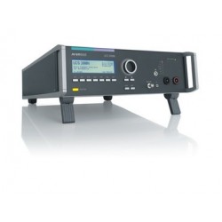
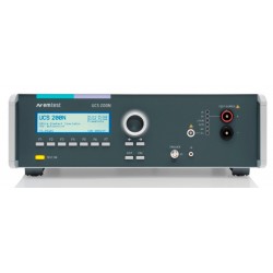
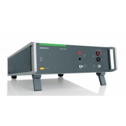
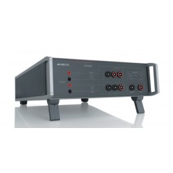
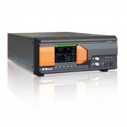
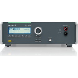
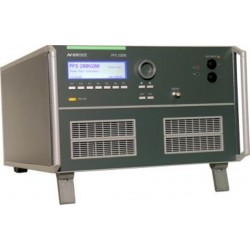
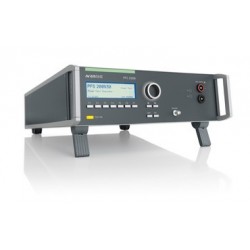
EM Test PFS 200N200 Power Fail Simulator 80V/200A
New
- 80V/200A Power Fail Simulator
- Standalone test generator for voltage dips and interruptions
- Rise/fall time <1us
- Electronic short-circuit protection
- Rated voltage 80V DC
- Front panel operation
- Standard Test routines
- USB and GPIB interfaces
PDF Downloads
Test Equipment Description
The PFS 200N Series Automotive Power Fail simulator is used to comply with standard requirements, mainly from vehicle manufacturers, to perform fast voltage dips ad drops (micro-interruptions). Some standards specify very fast rise and fall times below 1 microsecond an electronic switch.
Testing of electronic modules in 12V/24V or 42V supply systems. Short-term interruptions, micro dips and voltage drop out are causing malfunctions in electronic modules. These phenomena are simulated by the PFS 200N power fail generator. The PFS 200 can be used as an individual instrument or can be used in combination with all other generators of the series 200.
- Daimler Chrysler PF9326
- Ford ES-XW7T
- PSA B217110
- Renault 36.00.808
- Fiat 9.90110
Benefits
The PFS 200N is a standalone tester providing an electronic switch to perform voltage dips and drops (micro-interruptions) with fast rise and fall times of 1 microsecond. For voltage dips two DC voltage supplies are required while for for voltage drops (micro-interruptions) only one DC voltage supply is needed. The PFS 200N has the ability to control one external DC voltage source by means of an analog DC signal. The PFS 200N can also be easily integrated into a complete test set-up. Operation is possible both manually and by software via USB or GPIB. Fail inputs allow to control an ongoing test sequence based on the status of the DUT. Pre-programmed Standard Test routines allow highest user convenience. Still the PFS 200N offers the Quick Start test routine where parameters can be changed on-line during a test to evaluate the susceptibility level of an individual DUT.
Software
ISO.CONTROL - SOFTWARE FOR CONTROL AND DOCUMENTATION
Outstanding user convenience, clearly structured windows and operation features and the EM TEST standards library along with the flexibility to generate user specific test sequences very easily are the main features of iso.control software. The software is automatically configured according to the connected EM TEST generators. iso.control software covers international/national standards and most of the manufacturer standards and is continuously updated. Extensive reporting capabilities help the user to create test reports that meet international requirements. iso.control is supported by Windows XP, Windows Vista, Windows 7 and Windows 8. Remote control is achieved either via USB or GPIB. iso.control supports a wide range of GPIB cards of National Instruments.
Operation
EASY TO OPERATE
Front panel menu and function keys enable the user to program his test routines quickly and accurately. The cursor allows fast control of all test parameters of the programmed routine, thus test procedures are simplified and confidence is generated that every step is carried out correctly.
Auxilary Devices
RDS 200N - EXTERNAL CONTROLLED DC POWER SUPPLY In order to generate any voltages between the level of the battery supply and zero for voltage drops (micro-interruption) tests a controlled DC supply is needed. The RDS 200N perfectly fits these requirements and is controlled by the analog DC output signal of the PFS 200N. The RDS 200N is usually connected to the PF2 input of the PFS 200N.
Operating Functions
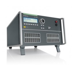
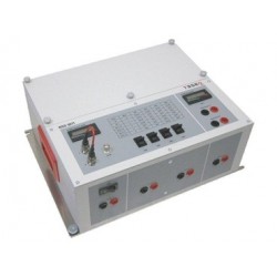
Front Panel | |
 | |
| 1 | Display All functions and parameters are displayed (8 lines with max. 40 characters). | 6 | Exit Pressing of the “EXIT” function will cause a reset of the firmware. This is only possible if no test routine is running. |
| 2 | Function keys “F1 .. F7” Parameters and functions, displayed in the lowest line, can be selected with the related function key. | 7 | ESC When pressing the ESC button the user moves back one page in the menu. |
| 3 | Test On By pressing the key “TEST ON” the test procedure is initiated with the preselected parameters. The yellow key is illuminated in TEST ON mode. | 8 | BNC CRO Trigger At the BNC plug CRO TRIGGER a signal is available to trigger an oscilloscope. (5V _ neg slope at ervent) |
| 4 | Knob (Inc / Dec) The knob increments or decrements test parameters with a numeric value or selects from a list of parameters. | 9 | LED channel mode The actual channel under control is indicated by LED. |
| 5 | Cursor keys Parameters and functions can be changed on-line. The selection of these parameters is realized with the cursor moving to the left or to the right. | 10 | EUT test supply The EUT is powered via the safety laboratory plugs at the front panel of the simulator. The nominal battery supply depend on the PFS200 model. |
Rear view | |
 | |
| 1 | Test supply output | 8 | Mains selector Selection 115V / 230V. |
| 2 | Test supply PF1 | 9 | Power on switch The switch is part of the mains filter. Mains fuses are part of the filter 230V/1A or 115V/2A |
| 3 | Reference ground connection | 10 | Parallel interface |
| 4 | Test supply PF2 The power supply for the EUT is connected to the banana connectors + / - . The power supply is connected to channel PF2. See par. 4 and 5 for connecting diagrams and detailed information. | 11 | USB interface USB interface “USB B” connector. For datatransfer a USB interface is available. The internal RS 232 interface is converted to USB standard. Therefore the user must set the same Baudrate in the device and control software. Using the USB interface the user can have emc problems during burst tests Our experiences says, that usually the computer USB port is disturbed by interference’s. Therefore a high quality USB cable ( USB 2.0 standard) must be used. |
| 5 | Ventilation | 12 | CN interface Device internal interface not used |
| 6 | Control voltage 0-10V The voltage is used to control external power sources. The source normally is connected to the channel PF2. The voltage level can be selected via the operating panel of the PFS. | 13 | Fail detection FAIL 1 (TEST STOP) The BNC input FAIL 1 can be used for failure detection at the EUT. If the input is set to ground (chassis) the PFS-generator will be stopped and the actual test routine is finished. It is not possible to continue this test routine. A complete restart of the routine is necessary. A message of FAIL 1 is indicated in the LCD display as well as in the ISM software. Fail detection FAIL 2 (TEST PAUSE) The BNC input FAIL 2 can be used for failure detection at the EUT. If the input is set to ground (chassis) the actual test routine is paused as long as the low level signal is available at the FAIL 2 input. Without the low level signal the test procedure continues automatically. A message of FAIL 2 is indicated in the LCD display as well as in the ISM software. |
| 7 | BNC EXT. TRIGGER One single event can be released. Trigger level +5 to +15V positive going. |
| Technical Data | |||||
| Power switches PFS200N Series | |||||
| Model | PFS200N30 | PFS200N50 | PFS200N100 | PFS200N150 | PFS200N200 |
| Channel PF1/PF2 | DC voltage max. 80 V | ||||
| Channel PF1 | DC current max. 32 A | DC current max. 50 A | DC current max. 100 A | DC current max. 150 A | DC current max. 200 A |
| Channel PF2 | DC current max. 50 A | DC current max. 100 A | DC current max. 150 A | DC current max. 200 A | |
| Switching time (on/off) | Open circuit < 1µs | ||||
| Inrush current | 70 A 500 ms | 100 A 500 ms | 150 A 500 ms | ||
| electronically overload protection protected against short circuit | Settable up to 32 A | 100 A 500 ms Settable up to 50 A | 150 A 500 ms Settable up to 100 A | Settable up to 150 A | Settable up to 200 A |
| Trigger | |||||
| Automatic | automatic release of the events | ||||
| Repetition rate | 0.1 s – 999 s | ||||
| Drop out duration td | .0µs - 9999ms | ||||
| Dip duration | 0.001ms – 1.00 ms step 0.001 ms | ||||
| Manual | Single event trigger | ||||
| External | Trigger by external signal | ||||
| Measurement | |||||
| BNC connector CRO I | internal current sensor for nominal current, inrush current 10mV / A max. 700A | ||||
| BNC connector CRO TRIGGER | trigger for oscilloscope positive ramp to +15V delay approx. 30ms | ||||
| Test routines | |||||
| Quick Start | All parameters adjustable while test is running | ||||
| Standard test Routines | 1. Chrysler PF 9326 2. Ford 3. PSA / Renault | ||||
| Service | Addresses Selftest Set-up | ||||
| Interfaces | |||||
| Serial Interface | USB Setting Baudrate (RS232: 9'600 , 19'200 Baud ) | ||||
| Parallel Interface IEEE | Addresses 1 – 30 | ||||
| Analogue output | 0 – 10V DC to control external voltage sources | ||||
| General | |||||
| Device | PFS 200N30,N50,N100 PFS 200N150, N200 | ||||
| Dimensions | 19” / 3 HU 19” / 6 HU | ||||
| Weight | N30 / N50: 10.8 kg N100: 14kg approx. 30 kg | ||||
| Power supply | 115/230V +10/-15% 50/60Hz (optional 115 V) Max. 60 VA | ||||
| Fuses | 2 * 1 A T | ||||
| Environmental conditions | |||||
| Temperature | 10 °C to 35 °C | ||||
| Humidity | 30 % to 70 %; non condensing Environmental conditions | ||||
| Atmospheric pressure | 86 kPa (860 mbar) to 106 kPa (1 060 mbar) | ||||
Associated EMC Test Equipment
30 other products in the same category:
-
EM Test UCS 200N50 Automotive Transient Simulator for Pulses 1, 2, 3A/3B
-
Rent EM Test VDS 200N10 Automotive Battery Source and Voltage Drop Simulator, 60 V/10 A
-
Haefely ONYX 30 ESD Simulator Gun for ISO 10605
-
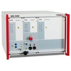
Teseq NSG 5500 Automotive Immunity Generator
-
Rent EM Test UCS 200N50 ISO 7637 EMC Generator for Automotive Waveforms 1,2a, 3a, 3b
-
EM Test AutoWave for Generating and Recording Automotive Waveforms
-
EM Test PFM 200N100.1 Automotive Power Fail Simulator for Power Supply and Data Lines
-
EM Test AMP 200N Low Frequency Signal Source DC (0Hz) to 250kHz
-
EM Test CN 200N1 Audio Transformer Assembly for LF Conducted Immunity Testing
-
Teseq PA 5740 Power Amplifier/Battery Simulator for ISO 7637
-
Teseq PA 5840 Power Amplifier/Battery Simulator for ISO 7637
-
Teseq NSG 5071 Inducitive Switch Transient Test Circuit
-
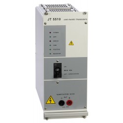
Teseq JT 5510 Transient Generator
-

EM Test VDS 200N10 Automotive Battery Source and Voltage Drop Simulator, 60 V/10 A
-
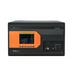
3ctest LDS 200 Load Dump Simulator, for ISO 16750-2 TEST A/B & ISO 7637-2 P5a/P5b, w/ built in 60V/30A Coupler
-
Teseq CDN 500 Capacitive Coupling Clamp for ISO 7637-3
-
Teseq INA 5530 ISO 7637 Automotive Pulse 3a & 3b Verification Kit
-

EM Test ACC Capacitive Coupling Clamp for ISO 7637 Automotive Testing
-
Rent 3ctest TIS 700 Automotive Transient Simulator ISO 7637 Pulse 1,2a,3a/b
-
EM Test PFS 200N30 Simulator for DC Voltage Drops & Micro-interruptions
-
EM Test LD 200N Automotive Load Dump Generator for ISO 7637 Pulses 5 and 7
-
EM Test MPG 200 Automotive Micropulse Generator up to 1.1 kV, built in CDN 60V/25A DC
-
Used Teseq NSG 5500-1 Automotive Test System
-
EM Test AN 200N100 Single line Artificial Network as per ISO 7637-2, CISPR25, ISO 11452 and CISPR16, switchable, 100A
-
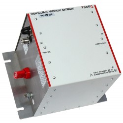
Teseq HV-AN 150 Artificial Network (AN) for Automotive, Airborne and MIL
-
EM Test PFS 200N50 Power Fail Simulator 80V/50A
-

EM Test PFS 200N100 Power Fail Simulator 80V/100A
-
EM Test PFS 200N150 Power Fail Simulator 80V/150A
-
Rent Amplifier Research ATH800M6G 800 MHz to 6 GHz High Gain Horn Antenna
-
EM Test PFS 200N Automotive Power Fail Simulator (Voltage Dips & Interruptions)