No products
Product successfully added to your shopping cart
There are 0 items in your cart. There is 1 item in your cart.
Antenna Test Turntables
- EMC Test Equipment
- Transient Generators
- RF Power Amplifiers
- DC - 300 kHz RF Amplifiers
- 10 kHz - 250 MHz RF Amplifiers
- 10 kHz - 400 MHz RF Amplifiers
- 10 kHz - 1 GHz RF Amplifiers
- 80 MHz - 1 GHz RF Amplifiers
- 1 GHz - 2 GHz RF Amplifiers
- 700 MHz - 4.2 GHz RF Amplifiers
- 1 GHz - 6 GHz RF Amplifiers
- 2 GHz - 8 GHz RF Amplifiers
- 6 GHz - 18 GHz RF Amplifiers
- 18 GHz - 40 GHz RF Amplifiers
- Pulse Amplifiers
- RF Field Strength Probes & Meters
- RF Conducted Immunity
- EMC Receivers/EMI Analyzers
- EMC Antennas
- Coupling Decoupling Networks (CDN's)
- Line Impedance Stabilization Networks (LISN's)
- RF Test Equipment
- EMC Probes
- EMC Measurement & Equipment Software
- Power Supplies
- Electrical Safety Analyzers
- High Precision Laboratory Power Analyzers & Meters
- Anechoic Chambers
- Over-the-Air (OTA) Test Chambers
- EMI RF Shielded Tent Enclosures
- RF Shielded Rooms
- EMC Absorber
- Positioning Equipment
- EMC/EMI Test Setup
- GTEM Cells / TEM Cells
- Reverberation Chambers
- Used RF Anechoic Chambers
- EMC Chamber Filters
- EMC Chamber Shielding Gaskets
- RF Shielded Doors
- Anechoic Chamber Accessories
- Fully Anechoic (FAR) Test Chambers
- Manufacturers
- 3ctest
- AE Techron
- AH Systems
- Amplifier Research
- Boonton
- Com-Power
- Diamond Engineering
- EM Test (Ametek CTS)
- EMC Partner
- EMC Test Design
- Empower High Power RF Amplifiers
- ETS-lindgren
- Log Periodic Dipole Array Antenna
- Near Field Probe Sets
- Double Ridge Horn Antennas
- Biconical Antennas
- Quad Ridge Horn Antennas
- Electric Field Probes
- GTEM's
- Positioners & Tripods
- Loop Antennas
- Biconilog Antennas
- LISN's (Line Impedance Stabilization Network)
- Shielded Enclosures/Rooms
- Monopole Antennas
- Field Generating Antennas
- Fischer Custom Communications
- Haefely Hipotronics
- Haefely EFT/Burst Immunity Test Systems
- Haefely Surge Combination Wave Test Systems
- Haefely Surge Damped Oscillating Wave Test Systems
- Haefely Electrostatic Discharge Test Systems (ESD)
- Haefely Surge Ring Wave Test Systems
- Haefely Surge Telecom Wave Test Systems
- Haefely Magnetic Field Test Systems
- Haefely CDN's (Coupling/Decoupling Networks)
- IFI Amplifiers
- Keysight (Agilent)
- MVG - Microwave Vision Group
- PMM / Narda
- Rohde & Schwarz RF Test Equipment
- Rohde & Schwarz Broadband RF Amplifiers
- Rohde & Schwarz Spectrum Analyzers
- Rohde & Schwarz Compliant EMI Test Receivers
- Rohde & Schwarz Isotropic RF Probes
- Rohde & Schwarz RF Signal Generators
- Rohde & Schwarz RF Switches
- Rohde & Schwarz Oscilloscopes
- Rohde & Schwarz RF Power Meters
- Rohde & Schwarz RF Power Sensors
- Schloder
- Schwarzbeck Mess-Elektronik
- Schwarzbeck Antennas
- Schwarzbeck Automotive Antennas
- Schwarzbeck Broadband Horn Antennas
- Schwarzbeck Biconical Antennas
- Schwarzbeck Logarithmic Periodic Broadband Antennas
- Schwarzbeck Stacked Log-Periodic Broadband Antennas
- Schwarzbeck Biconic Log-Periodic Antennas
- Schwarzbeck Dipole Antennas
- Schwarzbeck Rod Antennas
- Schwarbeck Antenna Baluns / Holders
- Schwarzbeck LISN Line Impedance Stabilisation Networks
- Schwarbeck Decoupling & Absorbing Clamps
- Schwarzbeck Field Probes
- Schwarzbeck Helmholtz Coils
- Schwarzbeck Antenna Masts
- Schwarzbeck Coupling/Decoupling Networks
- Schwarzbeck Antennas
- Solar Electronics
- Teseq (Schaffner)
- Teseq Automotive Transient Generators
- Teseq RF Test Equipment
- Teseq EFT/Burst Generators
- Teseq RF Immunity Generators
- Teseq ESD Guns
- Teseq Surge Generators
- Teseq Harmonics & Flicker Solutions
- Teseq Dips, Interrupts & Variations Equipment
- Teseq Ring Wave Generators
- Teseq Oscillatory Waves Generators
- Teseq Absorbing Clamps / Ferrite Tube
- Teseq EMC Antennas
- Teseq Current Probes
- Teseq Coupling Networks
- Thermo Keytek
- Vicreate
- Compliance Standards
- International (IEC/EN)
- EN/IEC 61000-3-2
- EN/IEC 61000-3-3
- IEC 61000-3-11
- IEC / EN 610000-3-12
- EN/IEC 61000-4-2
- EN/IEC 61000-4-3
- EN/IEC 61000-4-4
- EN/IEC 61000-4-5
- EN/IEC 61000-4-6
- EN/IEC 61000-4-7
- EN/IEC 61000-4-8
- EN/IEC 61000-4-9
- EN/IEC 61000-4-10
- EN/IEC 61000-4-11
- EN/IEC 61000-4-12
- EN/IEC 61000-4-16
- EN/IEC 61000-4-18
- EN/IEC 61000-4-19
- EN/IEC 61000-4-20
- EN/IEC 61000-4-21
- EN/IEC 61000-4-29
- EN/IEC 61000-4-31
- IEC 61000-4-39
- EN/IEC 62132
- SEMI F47 Voltage Sag Immunity
- Product Standards
- Military & Aerospace Standards
- Automotive EMC Standards
- CISPR Standards
- Telecom Testing
- ANSI/IEEE Standards
- FCC Part 15
- FCC Part 30
- International (IEC/EN)
- Application/Test Type
- Radiated Immunity
- Bulk Current Injection Testing
- RF Emissions Testing
- Conducted Immunity
- Conducted Emissions
- Antenna Pattern Measurement
- CE Mark Testing
- Intentional Radiator Testing
- Pulsed HIRF Radar
- Over-the-Air (OTA) Testing
- 5G Test Solutions
- Automotive EMC
- SAR Measurement Equipment
- Radiated Emissions
- Battery Simulator Test Equipment
- Services
- Clearance
Viewed products
-

Maturo FR-DYN-3t-F...
Free-standing version For use in...
-

Rohde & Schwarz TSEMF...
EMF Measurement probe Precise...
 View larger
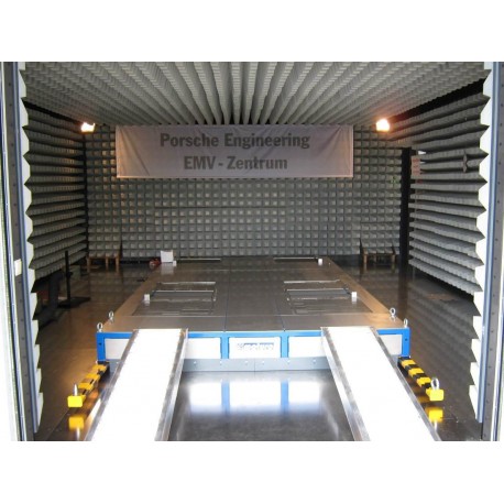
 Maturo FR-DYN-3t-F Free-Standing on Top of Hall Floor or Turntable
New
- Free-standing version
- For use in anechoic chambers for EMI and EMC measurements
- 2 passive axles, for cars with rear /front – or four wheel drive
- 4 free-running roller pairs, driven by the vehicle engine
- Removable, fixed on the turntable cover plates
- With loading ramps and bridges between both axles
- Optional mechanical coupling of front and rear axles available
PDF Downloads
Test Equipment Description

| Technical Data | |
| Permissible axle load | 1.500 kg (each axle) |
| Max speeds for cars | 100 km/h |
| Acceleration/ deceleration | max. 1.0g from 10 to 60 km/h |
| Wheel track between the front wheels | 1200 to 2100 mm |
| Wheelbase between the front and rear wheel | 1400 to 3200 mm |
| Diameter car wheels | min. 400 mm max. 800 mm |
| Diameter rollers (4 roller pairs) | 200 mm |
| The surface of the rollers is flame-coated The rollers are static heaved up to 2000 rpm | |
| Dimensions | |
| Housing frame L x W | approx. 4000 x 2500 mm |
| Overall Height | approx. 270 mm |
| Complete weight | approx. 2000 kg |
The Dynamometer FR-DYN-F is constructed as a freestanding dynamometer, which can be fixed onto a turntable or a stand-alone system. Two passive axles are used for vehicles with rear/front or four-wheel drive. The four independent roller pairs are free-running and operated by the vehicle engine.
Structure
The 4 independent roller pairs of the dynamometer are integrated into a “self-contained” frame, which minimize the dynamic energy output to the turntable or hall floor.
Rollers
The rollers are static heaved up to 2000 rpm and flame-coated.
The surface of the rollers is comparable with road surface.
Balance quality: Q 2.5 according to VDI 2060

Fig.: Double roller system
Wheel Base
The wheelbase is to adjust manually. The base must be adjusted according to the car wheel distance with a +/- 2 mm tolerance. Operation of the wheel base adjustment is only possible at a standstill of the dynamometer.
Loading and Unloading
To drive the car on the stand and into the rollers two free adjustable ramps and must be used. The ramps are removable while the test is running.

Fig.: Adjustable ramps
Fixing elements
The system is equipped with four lashing straps to fixing of the vehicle while running. Spring hooks allow an easy connection to the four fastening bolts. The fixing elements are integrated into the structure of the system and are adjustable to the specific vehicle sizes. The straps are made of electrically neutral material. Length adjustment: from 1.0 to 6.0 m Tensile strength: 5000 N

Fig.: Fixing system
Optional: Mechanical coupling of the axles
Both axles are firmly mechanically linked together for a synchronous operation of all rollers. This coupling prevents a response of all driving safety systems in the vehicle; e.g. ESP.

Fig.: Mechanical coupling of the axles
Option: Cooling Fan System
Shielded fans provide a sufficient cooling for the tyres and the motor of the vehicle under test.
The plastic air scoop on top of the turntable is used to detour the airflow.
The fan speed can be set either proportional to the roller speed (up to 60 km/h) or to a
constant speed by the NCD Controller.

Fig.: Cooling fan system
| Technical Data | |
| Wind speed | 60 km/h |
| Adjustable according to the vehicle speed | |
| Air flow | 10.000 m³/h |
| Outlet opening of air scoop | 1.0 x 0.3 m |
| Material of air scoop | Plastic and wood |
| Current consumption | max. 16A |
| Power consumption | 380-400 V/ 50-60 Hz/ 3-phase |
| Operating Temperature | 5°C to 40°C |
| Total weight | approx. 60 kg |
| With guide plates for adjustment of the direction of the wind 4 lockable castors for easy movement of the system | |


