
No products
Product successfully added to your shopping cart
There are 0 items in your cart. There is 1 item in your cart.
CISPR 16 LISN's
- EMC Test Equipment
- Transient Generators
- RF Power Amplifiers
- DC - 300 kHz RF Amplifiers
- 10 kHz - 250 MHz RF Amplifiers
- 10 kHz - 400 MHz RF Amplifiers
- 10 kHz - 1 GHz RF Amplifiers
- 80 MHz - 1 GHz RF Amplifiers
- 1 GHz - 2 GHz RF Amplifiers
- 700 MHz - 4.2 GHz RF Amplifiers
- 1 GHz - 6 GHz RF Amplifiers
- 2 GHz - 8 GHz RF Amplifiers
- 6 GHz - 18 GHz RF Amplifiers
- 18 GHz - 40 GHz RF Amplifiers
- Pulse Amplifiers
- RF Field Strength Probes & Meters
- RF Conducted Immunity
- EMC Receivers/EMI Analyzers
- EMC Antennas
- Coupling Decoupling Networks (CDN's)
- Line Impedance Stabilization Networks (LISN's)
- RF Test Equipment
- EMC Probes
- EMC Measurement & Equipment Software
- Power Supplies
- Electrical Safety Analyzers
- High Precision Laboratory Power Analyzers & Meters
- Anechoic Chambers
- Over-the-Air (OTA) Test Chambers
- EMI RF Shielded Tent Enclosures
- RF Shielded Rooms
- EMC Absorber
- Positioning Equipment
- EMC/EMI Test Setup
- GTEM Cells / TEM Cells
- Reverberation Chambers
- Used RF Anechoic Chambers
- EMC Chamber Filters
- EMC Chamber Shielding Gaskets
- RF Shielded Doors
- Anechoic Chamber Accessories
- Fully Anechoic (FAR) Test Chambers
- Manufacturers
- 3ctest
- AE Techron
- AH Systems
- Amplifier Research
- Boonton
- Com-Power
- Diamond Engineering
- EM Test (Ametek CTS)
- EMC Partner
- EMC Test Design
- Empower High Power RF Amplifiers
- ETS-lindgren
- Log Periodic Dipole Array Antenna
- Near Field Probe Sets
- Double Ridge Horn Antennas
- Biconical Antennas
- Quad Ridge Horn Antennas
- Electric Field Probes
- GTEM's
- Positioners & Tripods
- Loop Antennas
- Biconilog Antennas
- LISN's (Line Impedance Stabilization Network)
- Shielded Enclosures/Rooms
- Monopole Antennas
- Field Generating Antennas
- Fischer Custom Communications
- Haefely Hipotronics
- Haefely EFT/Burst Immunity Test Systems
- Haefely Surge Combination Wave Test Systems
- Haefely Surge Damped Oscillating Wave Test Systems
- Haefely Electrostatic Discharge Test Systems (ESD)
- Haefely Surge Ring Wave Test Systems
- Haefely Surge Telecom Wave Test Systems
- Haefely Magnetic Field Test Systems
- Haefely CDN's (Coupling/Decoupling Networks)
- IFI Amplifiers
- Keysight (Agilent)
- MVG - Microwave Vision Group
- PMM / Narda
- Rohde & Schwarz RF Test Equipment
- Rohde & Schwarz Broadband RF Amplifiers
- Rohde & Schwarz Spectrum Analyzers
- Rohde & Schwarz Compliant EMI Test Receivers
- Rohde & Schwarz Isotropic RF Probes
- Rohde & Schwarz RF Signal Generators
- Rohde & Schwarz RF Switches
- Rohde & Schwarz Oscilloscopes
- Rohde & Schwarz RF Power Meters
- Rohde & Schwarz RF Power Sensors
- Schloder
- Schwarzbeck Mess-Elektronik
- Schwarzbeck Antennas
- Schwarzbeck Automotive Antennas
- Schwarzbeck Broadband Horn Antennas
- Schwarzbeck Biconical Antennas
- Schwarzbeck Logarithmic Periodic Broadband Antennas
- Schwarzbeck Stacked Log-Periodic Broadband Antennas
- Schwarzbeck Biconic Log-Periodic Antennas
- Schwarzbeck Dipole Antennas
- Schwarzbeck Rod Antennas
- Schwarbeck Antenna Baluns / Holders
- Schwarzbeck LISN Line Impedance Stabilisation Networks
- Schwarbeck Decoupling & Absorbing Clamps
- Schwarzbeck Field Probes
- Schwarzbeck Helmholtz Coils
- Schwarzbeck Antenna Masts
- Schwarzbeck Coupling/Decoupling Networks
- Schwarzbeck Antennas
- Solar Electronics
- Teseq (Schaffner)
- Teseq Automotive Transient Generators
- Teseq RF Test Equipment
- Teseq EFT/Burst Generators
- Teseq RF Immunity Generators
- Teseq ESD Guns
- Teseq Surge Generators
- Teseq Harmonics & Flicker Solutions
- Teseq Dips, Interrupts & Variations Equipment
- Teseq Ring Wave Generators
- Teseq Oscillatory Waves Generators
- Teseq Absorbing Clamps / Ferrite Tube
- Teseq EMC Antennas
- Teseq Current Probes
- Teseq Coupling Networks
- Thermo Keytek
- Vicreate
- Compliance Standards
- International (IEC/EN)
- EN/IEC 61000-3-2
- EN/IEC 61000-3-3
- IEC 61000-3-11
- IEC / EN 610000-3-12
- EN/IEC 61000-4-2
- EN/IEC 61000-4-3
- EN/IEC 61000-4-4
- EN/IEC 61000-4-5
- EN/IEC 61000-4-6
- EN/IEC 61000-4-7
- EN/IEC 61000-4-8
- EN/IEC 61000-4-9
- EN/IEC 61000-4-10
- EN/IEC 61000-4-11
- EN/IEC 61000-4-12
- EN/IEC 61000-4-16
- EN/IEC 61000-4-18
- EN/IEC 61000-4-19
- EN/IEC 61000-4-20
- EN/IEC 61000-4-21
- EN/IEC 61000-4-29
- EN/IEC 61000-4-31
- IEC 61000-4-39
- EN/IEC 62132
- SEMI F47 Voltage Sag Immunity
- Product Standards
- Military & Aerospace Standards
- Automotive EMC Standards
- CISPR Standards
- Telecom Testing
- ANSI/IEEE Standards
- FCC Part 15
- FCC Part 30
- International (IEC/EN)
- Application/Test Type
- Radiated Immunity
- Bulk Current Injection Testing
- RF Emissions Testing
- Conducted Immunity
- Conducted Emissions
- Antenna Pattern Measurement
- CE Mark Testing
- Intentional Radiator Testing
- Pulsed HIRF Radar
- Over-the-Air (OTA) Testing
- 5G Test Solutions
- Automotive EMC
- SAR Measurement Equipment
- Radiated Emissions
- Battery Simulator Test Equipment
- Services
- Clearance
Viewed products
-

Schwarzbeck NSLK 8128...
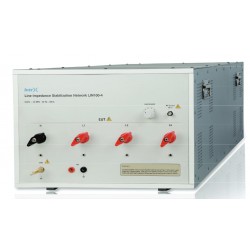
V-LISN 9 kHz - 30 MHz 50 µH + 5 Ohm...
-

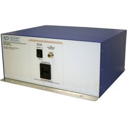
Agilent 8449B 26.5 GHz...
Sensitivity for MIL-STD radiated...
 View larger
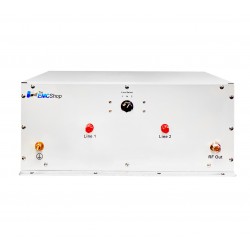
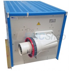
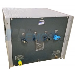
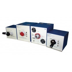
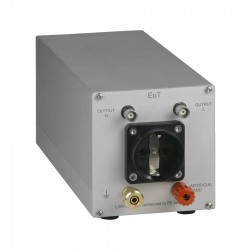
Schwarzbeck NSLK 8128 Line Impedance Stabilisation Network
New
- V-LISN
- 9 kHz - 30 MHz
- 50 µH + 5 Ohm || 50 Ohm
- 250 VAC / 400 VDC Maximum Voltage
- Artificial Hand
PDF Downloads
Test Equipment Description
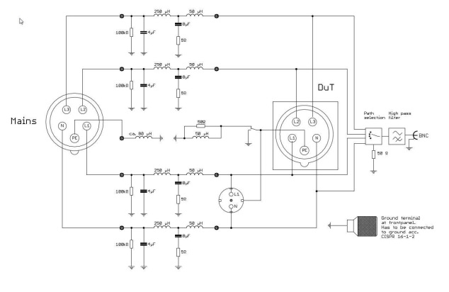
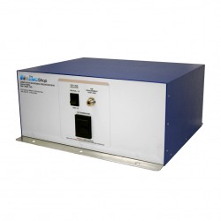
The NSLK 8128 is equipped with a 250 µH choke as well as with a 50 µH choke which is connected in series for each path. The 250 µH choke provides an excellent decoupling between the power supply and the device under test starting at 9 kHz.
Instructions for use:
The purpose of a LISN is to provide the device under test with energy, to carry the interference voltage to the EMI measurement receiver and to load the RF emitted by the device under test with standardized impedance.
Important! Connect the LISN to protecting earth BEFORE applying any voltage to it! For this purpose you can use the screw terminal at the front panel and the aluminum brackets at the rear side of the device.
Due to high capacities very high leakage currents can occur (above 1 A). Thus it is not possible to use a residual current operated circuit breaker. It is recommended to use an isolating transformer.
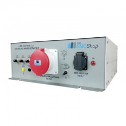
The supply voltage has to be applied at the back panel of the LISN by using the CEE connector.
Important! When using the Schuko connector the operator has to make sure that the maximum current is limited to 16 A at the supply side. When using the 32A CEE connector the current has to be limited to 32 A at the supply side. There is no fuse built into this LISN to protect the device under test!
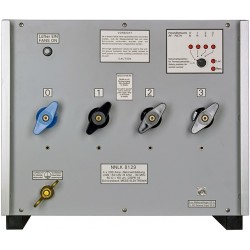
The device under test has to be connected to the Schuko socket or the CEE socket at the front panel. The maximum current that can be drawn is 32 A for each path when using the CEE connector and 16 A when using the Schuko socket. The maximum voltage that can be applied is 250 VAC or 400 VDC.
The input for the power supply is located at the back panel and provides a hard wired connection cable with a CEE plug.
The coaxial RF output has to be connected to the EMI measurement receiver using a BNC coaxial cable. You can choose the path that needs to be measured with the path selection switch. The path that is actually not measured will be terminated with 50 Ω automatically.
Protective earth switch
Using the switch labeled with “Safety ground” you can either put the protection earth of the Schuko socket straight to ground or in series with a parallel connection of a 50 µH choke and a 50 Ω resistor. Thus the protecting function of the protecting earth connector is ensured as long as the LISN is connected to earth properly.
A protective earth conductor that is decoupled RF-wise via the choke simulates the utilization of long cables. Since some interference suppression solutions are based on the protective ground conductor potential the emission of the device under test could vary depending on the switch setting.
“Artificial Hand”
If an "artificial hand" has to be connected to the equipment under test, a copper foil wrapped around the handle of the device under test has to be connected to the screw terminal labeled with “Hand Simulation”.
| Schwarzbeck NSLK 8128 Specifications | ||
| Topology: | V-LISN | |
| Frequency Range: | 9 kHz - 30 MHz | |
| Pre-filter choke: | 250 µH | |
| Impedance simulation: | 50 Ω || (50 µH + 5 Ω) | |
| Max. Current IEC 60309: | 4 x 32 A | |
| Max. Current CEE 7/4 socket: | 16 A | |
| max. Voltage: | 250 VAC 50/60 Hz 400 VDC | |
| Supply cable: | hard-wired five-wire connection cable with CEE plug (IEC 60309) | |
| Connector for EuT: | CEE 7/4 Type F (Schuko) socket and IEC 60309 3L+N+PE 32 A CEE socket | |
| Connector for "artificial hand": | 4 mm laboratory socket with screw terminal 6 mm, not removable | |
| Connector to EMI-receiver: | BNC socked, 50 Ω | |
| Length: | 470 mm | |
| Width: | 450 mm | |
| Height: | 370 mm | |
| Weight: | 34.2 kg (38.5 kg RC) | |
| Standard: | CISPR 16-1-2 | |
Associated EMC Test Equipment
27 other products in the same category:
-
LISN-CISPR16 25 Amp Line Impedance Stabilization Network 50μH/250μH
-
PMM L3-100 Three Phase 100 Amp LISN for CISPR 16-1-2
-
Com-Power LI-220C 9 kHz - 30 MHz LISN for CISPR 16-1-2/ANSI C63.4
-
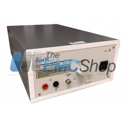
Intrx LIN16-2 Single Phase Two Wire LISN for CISPR 16-1-2
-
Com-Power LI-150A 150 kHz - 30 MHz LISN, 50 Amps, 50 uH for CISPR 16-1-2/ANSI C63.4
-
Schwarzbeck NNLK 8121 100 Amp Line Impedance Stabilization Network
-
Com-Power LI-3P-216 LISN, 9 kHz to 30 MHz, 50/250 uH, 500 VAC
-

Com-Power LI-3P-200 Series 3-Phase LISN's with 50/250 uH Inductor, FCC/EN/CISPR, up to 100 A, 150 kHz - 30 MHz
-

Com-Power LI-3P-132 150kHz to 30MHz Three-Phase Line Impedance Stabilization Network
-
Intrx Three Phase Four Wire LISN for CISPR 16-1-2
-
Com-Power LI-3100 Line Impedance Stabilization Network
-
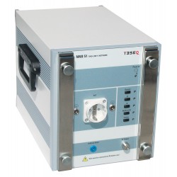
Teseq NNB 51 Line Impedance Stabilization Network Dual-Line-V-LISN
-
Com-Power LIN-120A LISN for CISPR 16-1-2/ANSI C63.4 w/ built-in Transient Limiter
-
Com-Power LI-220A 9 kHz - 30 MHz LISN for ISPR 16-1-2/ANSI C63.4
-
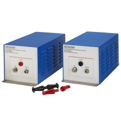
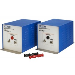
Com-Power LI-125C 150 kHz to 30 MHz Line Impedance Stabilization Network Pair
-

Com-Power LI-150C Line Impedance Stabilization Network
-
Rent Com-Power LI-3P-132 150kHz to 30MHz Three-Phase Line Impedance Stabilization Network
-
Schwarzbeck NNLK 8129 Line Impedance Stabilisation Network
-
Schwarzbeck NSLK 8126 Line Impedance Stabilisation Network
-
Schwarzbeck NNLK 8122 Line Impedance Stabilization Network
-
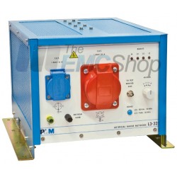
PMM L3-32 Four Line 3-Phase LISN w/ V-Network, 32 Amps AC+DC
-
Fischer Custom Communications FCC-LISN-50/250-16-2-01 Line Impedance Stabilization Network
-
Fischer Custom Communications FCC LISN-50/250/25-2 Line Impedance Stabilization Network
-
LISN-CISPR16-100 3-Phase, 100 Amp Line Impedance Stabilization Network
-
LISN-AC-CISPR16-10 Line Impedance Stabilization Network for CISPR16
-
LISN-CISPR16-32A Line Impedance Stabilization Network
-
LISN-AC-CIPSR16 9 kHz - 30 MHz for CISPR 16-1-2/ANSI C63.4