
No products
Product successfully added to your shopping cart
There are 0 items in your cart. There is 1 item in your cart.
EMC Receivers/EMI Analyzers
- EMC Test Equipment
- Transient Generators
- RF Power Amplifiers
- DC - 300 kHz RF Amplifiers
- 10 kHz - 250 MHz RF Amplifiers
- 10 kHz - 400 MHz RF Amplifiers
- 10 kHz - 1 GHz RF Amplifiers
- 80 MHz - 1 GHz RF Amplifiers
- 1 GHz - 2 GHz RF Amplifiers
- 700 MHz - 4.2 GHz RF Amplifiers
- 1 GHz - 6 GHz RF Amplifiers
- 2 GHz - 8 GHz RF Amplifiers
- 6 GHz - 18 GHz RF Amplifiers
- 18 GHz - 40 GHz RF Amplifiers
- Pulse Amplifiers
- RF Field Strength Probes & Meters
- RF Conducted Immunity
- EMC Receivers/EMI Analyzers
- EMC Antennas
- Coupling Decoupling Networks (CDN's)
- Line Impedance Stabilization Networks (LISN's)
- RF Test Equipment
- EMC Probes
- EMC Measurement & Equipment Software
- Power Supplies
- Electrical Safety Analyzers
- High Precision Laboratory Power Analyzers & Meters
- Anechoic Chambers
- Over-the-Air (OTA) Test Chambers
- EMI RF Shielded Tent Enclosures
- RF Shielded Rooms
- EMC Absorber
- Positioning Equipment
- EMC/EMI Test Setup
- GTEM Cells / TEM Cells
- Reverberation Chambers
- Used RF Anechoic Chambers
- EMC Chamber Filters
- EMC Chamber Shielding Gaskets
- RF Shielded Doors
- Anechoic Chamber Accessories
- Fully Anechoic (FAR) Test Chambers
- Manufacturers
- 3ctest
- AE Techron
- AH Systems
- Amplifier Research
- Boonton
- Com-Power
- Diamond Engineering
- EM Test (Ametek CTS)
- EMC Partner
- EMC Test Design
- Empower High Power RF Amplifiers
- ETS-lindgren
- Log Periodic Dipole Array Antenna
- Near Field Probe Sets
- Double Ridge Horn Antennas
- Biconical Antennas
- Quad Ridge Horn Antennas
- Electric Field Probes
- GTEM's
- Positioners & Tripods
- Loop Antennas
- Biconilog Antennas
- LISN's (Line Impedance Stabilization Network)
- Shielded Enclosures/Rooms
- Monopole Antennas
- Field Generating Antennas
- Fischer Custom Communications
- Haefely Hipotronics
- Haefely EFT/Burst Immunity Test Systems
- Haefely Surge Combination Wave Test Systems
- Haefely Surge Damped Oscillating Wave Test Systems
- Haefely Electrostatic Discharge Test Systems (ESD)
- Haefely Surge Ring Wave Test Systems
- Haefely Surge Telecom Wave Test Systems
- Haefely Magnetic Field Test Systems
- Haefely CDN's (Coupling/Decoupling Networks)
- IFI Amplifiers
- Keysight (Agilent)
- MVG - Microwave Vision Group
- PMM / Narda
- Rohde & Schwarz RF Test Equipment
- Rohde & Schwarz Broadband RF Amplifiers
- Rohde & Schwarz Spectrum Analyzers
- Rohde & Schwarz Compliant EMI Test Receivers
- Rohde & Schwarz Isotropic RF Probes
- Rohde & Schwarz RF Signal Generators
- Rohde & Schwarz RF Switches
- Rohde & Schwarz Oscilloscopes
- Rohde & Schwarz RF Power Meters
- Rohde & Schwarz RF Power Sensors
- Schloder
- Schwarzbeck Mess-Elektronik
- Schwarzbeck Antennas
- Schwarzbeck Automotive Antennas
- Schwarzbeck Broadband Horn Antennas
- Schwarzbeck Biconical Antennas
- Schwarzbeck Logarithmic Periodic Broadband Antennas
- Schwarzbeck Stacked Log-Periodic Broadband Antennas
- Schwarzbeck Biconic Log-Periodic Antennas
- Schwarzbeck Dipole Antennas
- Schwarzbeck Rod Antennas
- Schwarbeck Antenna Baluns / Holders
- Schwarzbeck LISN Line Impedance Stabilisation Networks
- Schwarbeck Decoupling & Absorbing Clamps
- Schwarzbeck Field Probes
- Schwarzbeck Helmholtz Coils
- Schwarzbeck Antenna Masts
- Schwarzbeck Coupling/Decoupling Networks
- Schwarzbeck Antennas
- Solar Electronics
- Teseq (Schaffner)
- Teseq Automotive Transient Generators
- Teseq RF Test Equipment
- Teseq EFT/Burst Generators
- Teseq RF Immunity Generators
- Teseq ESD Guns
- Teseq Surge Generators
- Teseq Harmonics & Flicker Solutions
- Teseq Dips, Interrupts & Variations Equipment
- Teseq Ring Wave Generators
- Teseq Oscillatory Waves Generators
- Teseq Absorbing Clamps / Ferrite Tube
- Teseq EMC Antennas
- Teseq Current Probes
- Teseq Coupling Networks
- Thermo Keytek
- Vicreate
- Compliance Standards
- International (IEC/EN)
- EN/IEC 61000-3-2
- EN/IEC 61000-3-3
- IEC 61000-3-11
- IEC / EN 610000-3-12
- EN/IEC 61000-4-2
- EN/IEC 61000-4-3
- EN/IEC 61000-4-4
- EN/IEC 61000-4-5
- EN/IEC 61000-4-6
- EN/IEC 61000-4-7
- EN/IEC 61000-4-8
- EN/IEC 61000-4-9
- EN/IEC 61000-4-10
- EN/IEC 61000-4-11
- EN/IEC 61000-4-12
- EN/IEC 61000-4-16
- EN/IEC 61000-4-18
- EN/IEC 61000-4-19
- EN/IEC 61000-4-20
- EN/IEC 61000-4-21
- EN/IEC 61000-4-29
- EN/IEC 61000-4-31
- IEC 61000-4-39
- EN/IEC 62132
- SEMI F47 Voltage Sag Immunity
- Product Standards
- Military & Aerospace Standards
- Automotive EMC Standards
- CISPR Standards
- Telecom Testing
- ANSI/IEEE Standards
- FCC Part 15
- FCC Part 30
- International (IEC/EN)
- Application/Test Type
- Radiated Immunity
- Bulk Current Injection Testing
- RF Emissions Testing
- Conducted Immunity
- Conducted Emissions
- Antenna Pattern Measurement
- CE Mark Testing
- Intentional Radiator Testing
- Pulsed HIRF Radar
- Over-the-Air (OTA) Testing
- 5G Test Solutions
- Automotive EMC
- SAR Measurement Equipment
- Radiated Emissions
- Battery Simulator Test Equipment
- Services
- Clearance
Viewed products
-

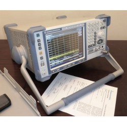
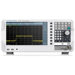
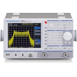
Rohde & Schwarz FSH3...
Frequency range up to 3 GHz Easy...


Rohde & Schwarz FSH3 Spectrum Analyzer
Refurbished
- Frequency range up to 3 GHz
- Easy operation, low weight and rugged design for field use
- Four hours operating time on battery power
- Storage of up to 256 traces and setups
- Easy data transfer to PC
- High measurement accuracy
PDF Downloads
Test Equipment Description
R&S®FSH Handheld Spectrum Analyzer
The R&S®FSH is the ideal spectrum analyzer for cost-effective signal investigations in the field. It provides a large number of measurement functions and so can handle anything from the installation or maintenance of a mobile radio base station up to on-site fault location in RF cables to development and service – an extensive range of applications.
Spectrum analysis anywhere, anytime on earth and in space
The FSH is the ideal spectrum analyzer for rapid, high-precision, cost-effective signal investigations. It provides a large number of measurement functions and so can handle anything from the installation or maintenance of a mobile radio base station up to on-site fault location in RF cables as well as development and service an extensive range of applications.
Handy, robust, and portable
The FSH has been designed as a robust, portable spectrum analyzer that can be used in the field.
- Robust edge protection, stable carrying handle
- Easy operation
- Four hours operating time on battery power
- Storage of up to 256 traces and setups
- Easy data transfer to PC
- High measurement accuracy
- Best RF characteristics in its class
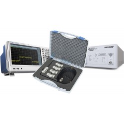
| The FSH can, of course, also be used on the lab bench. The FSH has an adjustable, fold-out stand to position the instrument to an optimal display viewing angle. | The FSH and its accessories can be stored and transported in the compact and sturdy aluminum transit case. |
 |  |
R&S®FSH FSH – options and applications
The R&S®FSH FSH can be used for measurements up to an upper frequency limit of 3 GHz, 6 GHz, and 18 GHz. The 3 GHz and 6 GHz are available with or without internal tracking generator. When the tracking generator is included, the R&S® FSH can be used for distance-to-fault (DTF) measurements, scalar and vector network analysis, and one-port cable loss measurement. Almost all models come standard with an adjustable preamplifier, making them suitable for measuring very small signals. Power sen- sors are available as accessories for high-precision terminating power measurements up to 8 GHz or 18 GHz as well as for directional power measurements up to 4 GHz. The following tables show possible configurations for various applications and an overview of available models.
TDMA Power MeasurementsBy means of the TDMA POWER function, the R&S®FSH performs time-domain power measurements within a timeslot of TDMA (time division multiple access) methods. All the settings required for the GSM and EDGE standards are predefined on the R&S®FSH to make these measurements easier for the user. In addition, up to five user-definable instrument setups can be loaded into the R&S®FSH using the R&S®FSH View software. |  |
Channel-power measurementsThe R&S®FSH determines the power of a definable transmission channel by means of the channel-power measurement function. A channel-power measurement for the digital mobile radio standards 3GPP WCDMA, cdmaOne, and CDMA2000® 1x is performed at a keystroke with all the correct instrument settings. With the R&S®View software, the user can quickly and easily define further standards and load them into the R&S®. |  |
Field-strength measurementsWhen measuring electric field strength, the R&S®FSH takes into account the specific antenna factors of the connected antenna. Field strength is displayed directly in dBµV/m. If W/m 2 is selected, the power flux density is calculated and displayed. In addition, frequency-dependent loss or gain of, for example, a cable or an amplifier can be corrected. For quick and easy result analysis, the ¸FSH provides two user-definable limit lines with automatic limit monitoring. R&S®FSH with R&S® TS-EMF isotropic antenna (optional accessory) |  |
Field-strength measurements with isotropic antennaWhen used with the R&S®TS-EMF isotropic antenna, the R&S®FSH can determine the direction-independent resultant field strength in the frequency range from 30 MHz to 3 GHz. For measuring the resultant field strength, the antenna has three orthogonal antenna elements. The R&S®FSH successively triggers the three antenna elements and calculates the resultant field strength. The calculation takes into account the antenna factors for each individual antenna element as well as the cable loss of the connecting cable. |  |
C/N MeasurementsThe R&S®FSH offers a carrier/noise (C/N) measurement for determining the ratio of carrier power to noise power or carrier power to noise power density. The R&S®FSH supports three different modes for carrier power measurement. In the CW TX mode, the R&S®FSH determines the power of an unmodulated carrier. In the digital TX mode, it determines the channel power of a reference channel, as is common with digitally modulated carriers (e.g. the DAB, DVB, DVB-T, DVB-H, and J.83/A/B/C standards). Furthermore, the ATSC standard for digital terrestrial television with 8VSB modulation is supported. In the analog TV mode, the R&S®FSH measures the peak power of the vision carrier with amplitude-modulated TV signals. |  |
Channel TablesIf preferred, the R&S®FSH can be tuned by channel numbers rather than by entering the frequency. The channel number is displayed instead of the center frequency. Users who are accustomed to channel assignments, which are common in TV and mobile radio applications, can operate the R&S®FSH more easily. The channel tables are generated with the R&S®FSH View software and loaded into the R&S®. The R&S®FSH includes TV channel tables for a number of countries. |
|
Receiver ModeWhen equipped with the R&S®FSH -K3 option, the R&S®FSH can be operated as a receiver for monitoring and precompliance EMC applications. Measure- ments are performed at a predefined frequency with a user-selectable measure- ment time. In the scan mode, the R&S®FSH sequentially measures each level at various frequencies defined in a channel table. The channel tables are generated with the R&S®View software and loaded into the R&S®FSH . For a few TV transmitter and mobile radio standards, the tables are predefined. In addition, the CISPR bandwidths 200 Hz, 9 kHz, 120 kHz, and 1 MHz are available for EMI emission measurements. The R&S®FSH offers peak, average, RMS, and quasi-peak detectors. |  |
Power MeasurementsThe R&S®FSH-Z1 and R&S®FSH-Z18 power sensors expand the R&S®FSH to a high-precision RF power meter up to 8 GHz and 18 GHz respectively. As with thermal sensors, the true RMS value of the measured signal is obtained over the entire measurement range of –67 dBm to +23 dBm irrespective of the signal waveform. In particular with modulated signals, additional measurement errors can thus be prevented, and handling becomes easy. |  |
Directional Power MeasurementsThe R&S®FSH-Z14 and R&S®FSH-Z44 directional power sensors turn the R&S®FSH into a full-fledged directional power meter with a frequency range of 25 MHz to 1 GHz and 200 MHz to 4 GHz. The R&S®FSH can then simultaneously measure the output power and the matching of transmitter system antennas under operating conditions. The power sensors measure average power up to 120 W and normally eliminate the need for any extra attenuators. They are compatible with the common standards GSM/EDGE, 3GPP WCDMA, cdmaOne, CDMA2000® 1x, DVB-T, and DAB. Additionally, the peak envelope power (PEP) can be determined up to a maximum of 300 W. |
|
Measurements on Cables (distance to fault)The R&S®FSH-B1 option allows the distance to any faults in an RF cable to be determined rapidly and accurately. Distance-to-fault measurements using the R&S®FSH-Z2/-Z3 VSWR bridge provide an immediate overview of the state of the device under test (return loss and distance, see figure). The marker-zoom function allows detailed analysis of faults with a resolution of up to 1024 pixel. (distance-to-fault measurement) and R&S®FSH-Z2/-Z3 (VSWR bridge) options installed |  |
Scalar Transmission and Reflection Measurements with VSWR BridgeThe R&S®FSH with built-in tracking generator rapidly determines the transmission characteristics of cables, filters, amplifiers, etc, with a minimum of effort. When equipped with the R&S®FSH-Z2/-Z3 VSWR bridge (10 MHz to 3 GHz/6 GHz), the R&S®FSH can also measure the matching (return loss, reflection coefficient, or VSWR) of an antenna, for example. The bridge is screw- connected directly to the R&S®’s RF input and tracking generator output without involving cumbersome, extra cabling. The innovative design of the R&S®FSH-Z3 VSWR bridge with integrated RF bypass switch allows the user to make spectrum and transmission measurements also with the bridge connected. Active components such as amplifiers can be supplied directly via the RF cable by means of the two integrated bias tees. |   R&S®FSH-Z3 VSWR bridge |
Vector Transmission and Reflection MeasurementsCompared to scalar transmission and reflection measurements, the R&S®FSH- K2 option offers a significant increase in measurement accuracy and number of measurement functions. In addition to the magnitude of S11 and S21, the phase, group delay, and electrical length of a DUT can be determined. The Smith chart allows simultaneous display of magnitude and phase in order to analyze the matching of an antenna in detail, for example. A user-definable limit line and a zoom function come in handy when evaluating the measurement results. Owing to a wide variety of marker formats, the measured values are displayed in virtually all the conventional formats used in network analysis. The input of a reference impedance permits measurements on DUTs whose impedance is not 50 Ω. To increase measurement accuracy, the R&S®FSH performs complex correction of the system errors after calibration. |  Measurement of magnitude and phase in Smith chart  Measurement of phase |
One-Port Cable Loss MeasurementsThe R&S®FSH with tracking generator and VSWR bridge can determine the cable loss of previously installed long cables without much effort. One end of the cable is connected to the VSWR bridge, and the other end is terminated with a short circuit or simply left open. The calculated cable loss represents the average value within the displayed frequency range. The loss at specific frequencies is determined via markers. The one-port cable loss measurement is only available with the R&S®FSH-K2 option. |  |
3GPP FDD code domain power measurements on base stationsThe R&S®FSH-K4 option 1) allows code domain power measurements on a 3GPP base station. It measures the total power and the power of the most important code channels, such as the common pilot channel (CPICH), primary common control physical channel (P-CCPCH), primary synchronization channel (P-SCH), and secondary synchronization channel (S-SCH). Furthermore, the carrier frequency offset and the error vector magnitude (EVM) are measured and displayed. The scrambling code can be determined at the press of a button and used automatically for decoding the code channels. The user can also get a quick overview of adjacent base stations. The R&S®FSH can display up to eight scrambling codes with their CPICH power. The R&S®FSH-K4 option provides automatic level setting for fast and optimal setting of the reference level. In practice, this means very easy operation. To display the code domain power measurement values, only four operating steps are necessary:
|  1) Available for the R&S®3 (model .23) with serial number 103500 or later. |
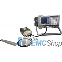
Locating EMC Weak SpotsThe R&S®HZ-15 near-field probe set is a diagnostic tool for locating EMC weak spots on printed boards, integrated circuits, cables, shieldings, and other trouble spots. The R&S®HZ-15 near-field probe set can handle emission measurements from 30 MHz to 3 GHz. Its sensitivity can be enhanced by adding the R&S®HZ-16 preamplifier, which has a frequency range of up to 3 GHz, a gain of approx. 20 dB, and a noise figure of 4.5 dB. In combination with the R&S®, the preamplifier and near-field probe set are a cost-effective means of analyzing and locating sources of interference during development. |  R&S®FSH with near-field probe set and DUT |


30 other products in the same category:
-
Rent Keysight N9048B CISPR 16 EMI Receiver
-
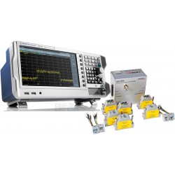
Rigol EMI Precompliance Test Equipment Bundle
-
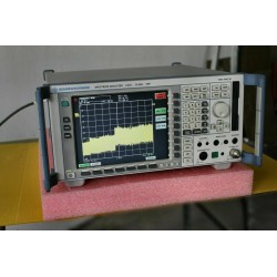
Used Rohde & Schwarz FSP38 9 kHz to 40 GHz Spectrum Analyzer
-
Rohde & Schwarz ESRP3 EMI Test Receiver per CISPR 16-1-1
-
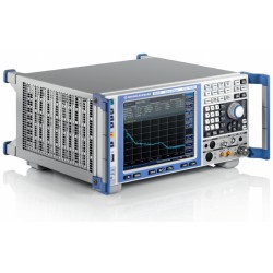
Rohde & Schwarz ESW Series EMI Test Receiver for CISPR16-1-1, 2 Hz to 8 GHz
-
Rohde & Schwarz ESRP7 EMI Test Receiver per CISPR 16-1-1, 9 kHz to 7 GHz
-
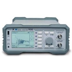
PMM 9010 EMC/EMI Digital Receiver per CISPR 16-1-1
-
Rohde & Schwarz FPC1000 Low-Cost Spectrum Analyzer for Emissions Testing
-
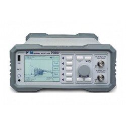
PMM 9010F CISPR 16-1-1 and MIL-STD-461 Compliant EMC/EMI Receiver
-
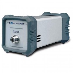
PMM-9030 9010 3GHz Extension Unit
-
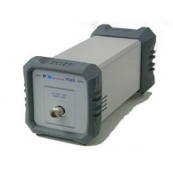
PMM-9060 EMC/EMI Digital Receiver
-
Narda PMM 7010 EMI Test Receiver
-
Rent Agilent (HP) E7401A EMC Analyzer, 9 kHz to 1.5 GHz
-
Rent Rohde & Schwarz ESU40 EMI Test Receiver for CISPR and MIL-STD Testing
-
Agilent (HP) 84115EM EMC Precompliance Test System
-
Keysight 34460A Digital Truevolt Multimeter, 100 mV to 1,000 V DCV, 100 mV to 750 V ACV
-

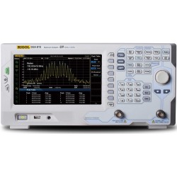
Rigol DSA710 100kHz to 1GHz Spectrum Analyzer
-

Com-Power SPA-815TGE 9 kHz to 1.5 GHz Rigol Spectrum Analyzer with Tracking Generator & EMI Option
-

Com-Power SPA-832TGE 9 kHz to 3.2 GHz Rigol Spectrum Analyzer with Tracking Generator & EMI Option
-
Com-Power SPA-875TGE 9 kHz to 7.5 GHz Rigol Spectrum Analyzer with Tracking Generator & EMI Option
-
Rent Rigol DSA710 100kHz to 1GHz Spectrum Analyzer
-
Rohde & Schwarz HMS-X Spectrum Analyzer
-
Rohde & Schwarz Precompliance EMI Emissions Test Equipment Package
-
Rohde & Schwarz Ethernet Radiated Emissions Test Equipment Package
-
Rohde & Schwarz FSV40 10 Hz - 40 GHz Spectrum Analyzer
-
Rohde & Schwarz FSP30 9 kHz to 30 GHz Spectrum Analyzer Rental
-

Rigol DSA1030A Spectrum Analyzer LXI 9kHz - 3GHz
-
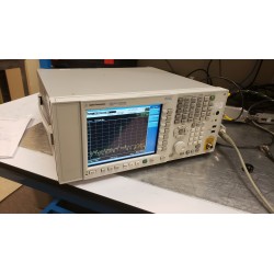
Keysight (Agilent) N9010A EXA Signal Analyzer, 9 kHz - 3.6 GHz
-
Keysight (Agilent) N9030A PXA Signal Analyzer, 3 Hz to 50 GHz
-
Aaronia Spectran V5 Real Time Spectrum Analyzer 9kHz-20GHz HF-80200 W/ RTSA Pro