
No products
Product successfully added to your shopping cart
There are 0 items in your cart. There is 1 item in your cart.
ISO 11452-4 Turnkey Systems
- EMC Test Equipment
- Transient Generators
- RF Power Amplifiers
- DC - 300 kHz RF Amplifiers
- 10 kHz - 250 MHz RF Amplifiers
- 10 kHz - 400 MHz RF Amplifiers
- 10 kHz - 1 GHz RF Amplifiers
- 80 MHz - 1 GHz RF Amplifiers
- 1 GHz - 2 GHz RF Amplifiers
- 700 MHz - 4.2 GHz RF Amplifiers
- 1 GHz - 6 GHz RF Amplifiers
- 2 GHz - 8 GHz RF Amplifiers
- 6 GHz - 18 GHz RF Amplifiers
- 18 GHz - 40 GHz RF Amplifiers
- Pulse Amplifiers
- RF Field Strength Probes & Meters
- RF Conducted Immunity
- EMC Receivers/EMI Analyzers
- EMC Antennas
- Coupling Decoupling Networks (CDN's)
- Line Impedance Stabilization Networks (LISN's)
- RF Test Equipment
- EMC Probes
- EMC Measurement & Equipment Software
- Power Supplies
- Electrical Safety Analyzers
- High Precision Laboratory Power Analyzers & Meters
- Anechoic Chambers
- Over-the-Air (OTA) Test Chambers
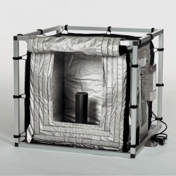
- EMI RF Shielded Tent Enclosures
- RF Shielded Rooms
- EMC Absorber
- Positioning Equipment
- EMC/EMI Test Setup
- GTEM Cells / TEM Cells
- Reverberation Chambers
- Used RF Anechoic Chambers
- EMC Chamber Filters
- EMC Chamber Shielding Gaskets
- RF Shielded Doors
- Anechoic Chamber Accessories
- Fully Anechoic (FAR) Test Chambers
- Manufacturers
- 3ctest
- AE Techron
- AH Systems
- Amplifier Research
- Boonton
- Com-Power
- Diamond Engineering
- EM Test (Ametek CTS)
- EMC Partner
- EMC Test Design
- Empower High Power RF Amplifiers
- ETS-lindgren
- Log Periodic Dipole Array Antenna
- Near Field Probe Sets
- Double Ridge Horn Antennas
- Biconical Antennas
- Quad Ridge Horn Antennas
- Electric Field Probes
- GTEM's
- Positioners & Tripods
- Loop Antennas
- Biconilog Antennas
- LISN's (Line Impedance Stabilization Network)
- Shielded Enclosures/Rooms
- Monopole Antennas
- Field Generating Antennas
- Fischer Custom Communications
- Haefely Hipotronics
- Haefely EFT/Burst Immunity Test Systems
- Haefely Surge Combination Wave Test Systems
- Haefely Surge Damped Oscillating Wave Test Systems
- Haefely Electrostatic Discharge Test Systems (ESD)
- Haefely Surge Ring Wave Test Systems
- Haefely Surge Telecom Wave Test Systems
- Haefely Magnetic Field Test Systems
- Haefely CDN's (Coupling/Decoupling Networks)
- IFI Amplifiers
- Keysight (Agilent)
- MVG - Microwave Vision Group
- PMM / Narda
- Rohde & Schwarz RF Test Equipment
- Rohde & Schwarz Broadband RF Amplifiers
- Rohde & Schwarz Spectrum Analyzers
- Rohde & Schwarz Compliant EMI Test Receivers
- Rohde & Schwarz Isotropic RF Probes
- Rohde & Schwarz RF Signal Generators
- Rohde & Schwarz RF Switches
- Rohde & Schwarz Oscilloscopes
- Rohde & Schwarz RF Power Meters
- Rohde & Schwarz RF Power Sensors
- Schloder
- Schwarzbeck Mess-Elektronik
- Schwarzbeck Antennas
- Schwarzbeck Automotive Antennas
- Schwarzbeck Broadband Horn Antennas
- Schwarzbeck Biconical Antennas
- Schwarzbeck Logarithmic Periodic Broadband Antennas
- Schwarzbeck Stacked Log-Periodic Broadband Antennas
- Schwarzbeck Biconic Log-Periodic Antennas
- Schwarzbeck Dipole Antennas
- Schwarzbeck Rod Antennas
- Schwarbeck Antenna Baluns / Holders
- Schwarzbeck LISN Line Impedance Stabilisation Networks
- Schwarbeck Decoupling & Absorbing Clamps
- Schwarzbeck Field Probes
- Schwarzbeck Helmholtz Coils
- Schwarzbeck Antenna Masts
- Schwarzbeck Coupling/Decoupling Networks
- Schwarzbeck Antennas
- Solar Electronics
- Teseq (Schaffner)
- Teseq Automotive Transient Generators
- Teseq RF Test Equipment
- Teseq EFT/Burst Generators
- Teseq RF Immunity Generators
- Teseq ESD Guns
- Teseq Surge Generators
- Teseq Harmonics & Flicker Solutions
- Teseq Dips, Interrupts & Variations Equipment
- Teseq Ring Wave Generators
- Teseq Oscillatory Waves Generators
- Teseq Absorbing Clamps / Ferrite Tube
- Teseq EMC Antennas
- Teseq Current Probes
- Teseq Coupling Networks
- Thermo Keytek
- Vicreate
- Compliance Standards
- International (IEC/EN)
- EN/IEC 61000-3-2
- EN/IEC 61000-3-3
- IEC 61000-3-11
- IEC / EN 610000-3-12
- EN/IEC 61000-4-2
- EN/IEC 61000-4-3
- EN/IEC 61000-4-4
- EN/IEC 61000-4-5
- EN/IEC 61000-4-6
- EN/IEC 61000-4-7
- EN/IEC 61000-4-8
- EN/IEC 61000-4-9
- EN/IEC 61000-4-10
- EN/IEC 61000-4-11
- EN/IEC 61000-4-12
- EN/IEC 61000-4-16
- EN/IEC 61000-4-18
- EN/IEC 61000-4-19
- EN/IEC 61000-4-20
- EN/IEC 61000-4-21
- EN/IEC 61000-4-29
- EN/IEC 61000-4-31
- IEC 61000-4-39
- EN/IEC 62132
- SEMI F47 Voltage Sag Immunity
- Product Standards
- Military & Aerospace Standards
- Automotive EMC Standards
- CISPR Standards
- Telecom Testing
- ANSI/IEEE Standards
- FCC Part 15
- FCC Part 30
- International (IEC/EN)
- Application/Test Type
- Radiated Immunity
- Bulk Current Injection Testing
- RF Emissions Testing
- Conducted Immunity
- Conducted Emissions
- Antenna Pattern Measurement
- CE Mark Testing
- Intentional Radiator Testing
- Pulsed HIRF Radar
- Over-the-Air (OTA) Testing
- 5G Test Solutions
- Automotive EMC
- SAR Measurement Equipment
- Radiated Emissions
- Battery Simulator Test Equipment
- Services
- Clearance
Viewed products
-

ISO 11452-4 Turn Key...
Complete kit for ISO 11452-4 EMC...
") View larger
View larger ")
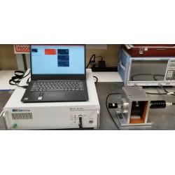
ISO 11452-4 Turn Key Solution for Harness Excitation Methods (BCI and TWC)
New
- Complete kit for ISO 11452-4 EMC Testing
- Test methods include
- Bulk Current Injection (BCI)
- Tubular Wave Coupler (TWC)
Test Equipment Description
ISO 11452-4 Overview
ISO 11452 specifies harness excitation test methods and procedures for determining the immunity of electronic components of passenger cars and commercial vehicles regardless of the propulsion system (e.g. spark-ignition engine, diesel engine, electric motor).
The bulk current injection (BCI) test method is based on current injection into the wiring harness using a current probe as a transformer where the harness forms the secondary winding.
The tubular wave coupler (TWC) test method is based on a wave coupling into the wiring harness using the directional coupler principle. The TWC test method was developed for immunity testing of automotive components with respect to radiated disturbances in the GHz ranges (GSM bands, UMTS, ISM 2,4 GHz). It is best suited to small (with respect to wavelength) and shielded device under test (DUT), since in these cases the dominating coupling mechanism is via the harness. For DUTs which are larger than a wavelength (e.g. 0,1 m at 3 GHz), direct field coupling to the printed circuit board (PCB) becomes of equal importance. The user of the TWC test method should take this into account and determine the applicability of the method. The electromagnetic disturbances considered in this part of ISO 11452 are limited to continuous narrowband electromagnetic fields.
Turn Key Solution for ISO 11452-4 Includes:
The EMC Shop can provide a variety of combinations from our trusted manufactures to satisfy 11452-4 testing specifications. Equipment combinations include but not limited to the following:
| Equipment Required (as per ISO 11452-4) | Equipment Solution(s) | ||
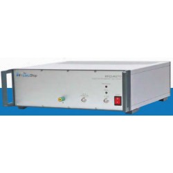
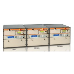
| Power Amplifier | EM Test CWS 500N1.3 EM Test CWS 500N2.2 EM Test CWS 500N2.3 EM Test CWS 500D | ||
Power measuring instrumentation forward/reverse power | | ||
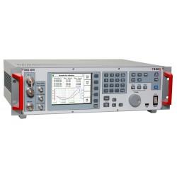
| RF generator with internal or external modulation capability | |||
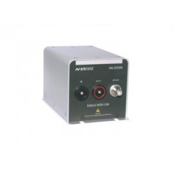
| Artificial networks(s) [AN(s)]; | EM Test AN 2050N | Narda PMM LISN | |
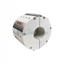
| RF Coupler | Teseq DCP 0100 Dual Directional Coupler | ||
| Monitoring probe | Teseq MD 4070 | ||
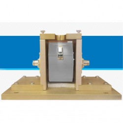
| Calibration jig | Teseq PCJ 9201B | ||
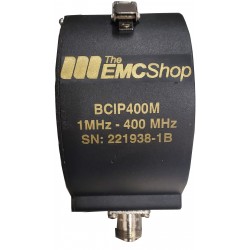
- of the BCI test method is 1 MHz to 400 MHz
- of the TWC test method is 400 MHz to 3 GHz
BCI test method
BCI is a method of carrying out immunity tests by inducing disturbance signals directly into the wiring harness by means of a current injection probe. The injection probe is a current transformer through which the wiring harnesses of the device under test (DUT) are passed. Immunity tests are carried out by varying the test severity level and frequency of the induced disturbance.
The following equipment is used:
— ground plane;
— current injection probe(s);
— current measurement probe(s);
— artificial network(s) [AN(s)];
— radio frequency (RF) generator with internal or external modulation capability;
— power amplifier;
— power measuring instrumentation to measure the forward and reverse power;
— current measurement equipment.
TWC test method
The approach of this test method is an equivalent coupling to a plane wave coupling into a wiring harness of automotive components. To realize this, a short 50 Ω coaxial line configuration with open ends, an inner tubeshaped conductor and matched terminations are used to generate a transverse electromagnetic (TEM) wave inside. The wiring harness leads through the inner conductor of the wave coupler. This leads to two disturbing components for the DUT: a TEM wave component coupled via the cable, and a radiated component, caused by the scattering field from the primary TEM wave in the connecting cable between the coupler and the DUT.
The following equipment is used:
— ground plane;
— tubular wave coupler;
— artificial networks(s) [AN(s)];
— RF generator with internal or external modulation capability;
— power amplifier;
— power measuring instrumentation to measure the forward and reverse power.
Associated EMC Test Equipment


8 other products in the same category:
-
RFCI-Auto Conducted Immunity Test System for ISO 11452-4
-
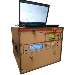
Rent Teseq NSG 4070C-45 Test System for Conducted & Radiated Immunity
-
AR CI00 Series RF Conducted Immunity Systems
-
Amplifier Research CI00400AM4 BCI RF Conducted Immunity Generator
-
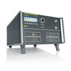
EM Test CWS 500N2 RF Conducted Immunity/BCI for Automotive & Mil-Std 461 CS 114
-
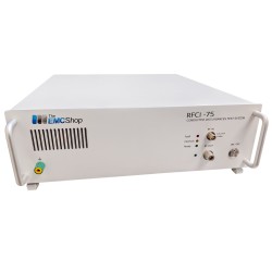
RFCI-75 RF Conducted Immunity Generator, 100 kHz - 400 MHz
-

Bulk Current Injection Test Setup - 400mA Automotive
-
Bulk Current Injection Test Setup - 10 Vrms IEC