
No products
Product successfully added to your shopping cart
There are 0 items in your cart. There is 1 item in your cart.
Bulk Current Injection Testing
- EMC Test Equipment
- Transient Generators
- RF Power Amplifiers
- DC - 300 kHz RF Amplifiers
- 10 kHz - 250 MHz RF Amplifiers
- 10 kHz - 400 MHz RF Amplifiers
- 10 kHz - 1 GHz RF Amplifiers
- 80 MHz - 1 GHz RF Amplifiers
- 1 GHz - 2 GHz RF Amplifiers
- 700 MHz - 4.2 GHz RF Amplifiers
- 1 GHz - 6 GHz RF Amplifiers
- 2 GHz - 8 GHz RF Amplifiers
- 6 GHz - 18 GHz RF Amplifiers
- 18 GHz - 40 GHz RF Amplifiers
- Pulse Amplifiers
- RF Field Strength Probes & Meters
- RF Conducted Immunity
- EMC Receivers/EMI Analyzers
- EMC Antennas
- Coupling Decoupling Networks (CDN's)
- Line Impedance Stabilization Networks (LISN's)
- RF Test Equipment
- EMC Probes
- EMC Measurement & Equipment Software
- Power Supplies
- Electrical Safety Analyzers
- High Precision Laboratory Power Analyzers & Meters
- Anechoic Chambers
- Over-the-Air (OTA) Test Chambers
- EMI RF Shielded Tent Enclosures
- RF Shielded Rooms
- EMC Absorber
- Positioning Equipment
- EMC/EMI Test Setup
- GTEM Cells / TEM Cells
- Reverberation Chambers
- Used RF Anechoic Chambers
- EMC Chamber Filters
- EMC Chamber Shielding Gaskets
- RF Shielded Doors
- Anechoic Chamber Accessories
- Fully Anechoic (FAR) Test Chambers
- Manufacturers
- 3ctest
- AE Techron
- AH Systems
- Amplifier Research
- Boonton
- Com-Power
- Diamond Engineering
- EM Test (Ametek CTS)
- EMC Partner
- EMC Test Design
- Empower High Power RF Amplifiers
- ETS-lindgren
- Log Periodic Dipole Array Antenna
- Near Field Probe Sets
- Double Ridge Horn Antennas
- Biconical Antennas
- Quad Ridge Horn Antennas
- Electric Field Probes
- GTEM's
- Positioners & Tripods
- Loop Antennas
- Biconilog Antennas
- LISN's (Line Impedance Stabilization Network)
- Shielded Enclosures/Rooms
- Monopole Antennas
- Field Generating Antennas
- Fischer Custom Communications
- Haefely Hipotronics
- Haefely EFT/Burst Immunity Test Systems
- Haefely Surge Combination Wave Test Systems
- Haefely Surge Damped Oscillating Wave Test Systems
- Haefely Electrostatic Discharge Test Systems (ESD)
- Haefely Surge Ring Wave Test Systems
- Haefely Surge Telecom Wave Test Systems
- Haefely Magnetic Field Test Systems
- Haefely CDN's (Coupling/Decoupling Networks)
- IFI Amplifiers
- Keysight (Agilent)
- MVG - Microwave Vision Group
- PMM / Narda
- Rohde & Schwarz RF Test Equipment
- Rohde & Schwarz Broadband RF Amplifiers
- Rohde & Schwarz Spectrum Analyzers
- Rohde & Schwarz Compliant EMI Test Receivers
- Rohde & Schwarz Isotropic RF Probes
- Rohde & Schwarz RF Signal Generators
- Rohde & Schwarz RF Switches
- Rohde & Schwarz Oscilloscopes
- Rohde & Schwarz RF Power Meters
- Rohde & Schwarz RF Power Sensors
- Schloder
- Schwarzbeck Mess-Elektronik
- Schwarzbeck Antennas
- Schwarzbeck Automotive Antennas
- Schwarzbeck Broadband Horn Antennas
- Schwarzbeck Biconical Antennas
- Schwarzbeck Logarithmic Periodic Broadband Antennas
- Schwarzbeck Stacked Log-Periodic Broadband Antennas
- Schwarzbeck Biconic Log-Periodic Antennas
- Schwarzbeck Dipole Antennas
- Schwarzbeck Rod Antennas
- Schwarbeck Antenna Baluns / Holders
- Schwarzbeck LISN Line Impedance Stabilisation Networks
- Schwarbeck Decoupling & Absorbing Clamps
- Schwarzbeck Field Probes
- Schwarzbeck Helmholtz Coils
- Schwarzbeck Antenna Masts
- Schwarzbeck Coupling/Decoupling Networks
- Schwarzbeck Antennas
- Solar Electronics
- Teseq (Schaffner)
- Teseq Automotive Transient Generators
- Teseq RF Test Equipment
- Teseq EFT/Burst Generators
- Teseq RF Immunity Generators
- Teseq ESD Guns
- Teseq Surge Generators
- Teseq Harmonics & Flicker Solutions
- Teseq Dips, Interrupts & Variations Equipment
- Teseq Ring Wave Generators
- Teseq Oscillatory Waves Generators
- Teseq Absorbing Clamps / Ferrite Tube
- Teseq EMC Antennas
- Teseq Current Probes
- Teseq Coupling Networks
- Thermo Keytek
- Vicreate
- Compliance Standards
- International (IEC/EN)
- EN/IEC 61000-3-2
- EN/IEC 61000-3-3
- IEC 61000-3-11
- IEC / EN 610000-3-12
- EN/IEC 61000-4-2
- EN/IEC 61000-4-3
- EN/IEC 61000-4-4
- EN/IEC 61000-4-5
- EN/IEC 61000-4-6
- EN/IEC 61000-4-7
- EN/IEC 61000-4-8
- EN/IEC 61000-4-9
- EN/IEC 61000-4-10
- EN/IEC 61000-4-11
- EN/IEC 61000-4-12
- EN/IEC 61000-4-16
- EN/IEC 61000-4-18
- EN/IEC 61000-4-19
- EN/IEC 61000-4-20
- EN/IEC 61000-4-21
- EN/IEC 61000-4-29
- EN/IEC 61000-4-31
- IEC 61000-4-39
- EN/IEC 62132
- SEMI F47 Voltage Sag Immunity
- Product Standards
- Military & Aerospace Standards
- Automotive EMC Standards
- CISPR Standards
- Telecom Testing
- ANSI/IEEE Standards
- FCC Part 15
- FCC Part 30
- International (IEC/EN)
- Application/Test Type
- Radiated Immunity
- Bulk Current Injection Testing
- RF Emissions Testing
- Conducted Immunity
- Conducted Emissions
- Antenna Pattern Measurement
- CE Mark Testing
- Intentional Radiator Testing
- Pulsed HIRF Radar
- Over-the-Air (OTA) Testing
- 5G Test Solutions
- Automotive EMC
- SAR Measurement Equipment
- Radiated Emissions
- Battery Simulator Test Equipment
- Services
- Clearance
Viewed products
-

Bulk Current Injection...
Bulk Current Injection Test Setup -...
 View larger

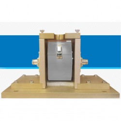
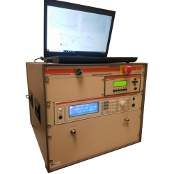
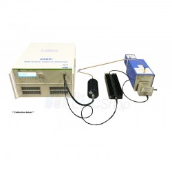
Bulk Current Injection Test Setup - 10 Vrms IEC
Rental
- Bulk Current Injection Test Setup - 10 Vrms IEC
- Complete, easy to setup test kit for EN/IEC61000-4-6 BCI Testing
- Pre-programmed test sequences and calibration files
- Ships immediately
In Stock
Specifications
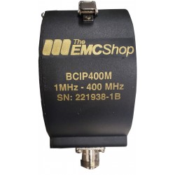
| Frequency range | 1 MHz - 400 MHz |
Test Equipment Description
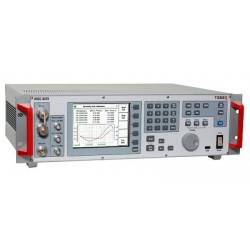
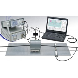
The EMC Shop stocks equipment systems to give customers immediate capability to bring a bulk current injection testing setup in house. Capable of achieving 10Vrms (Contact us for higher levels) per the IEC/EN 61000-4-6 BCI test standard. Technical support, manuals and video overviews are available to shorten the learning curve and get you up and testing efficiently.
Bulk Current Injection Test Setup - 10 Vrms IEC Includes
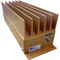
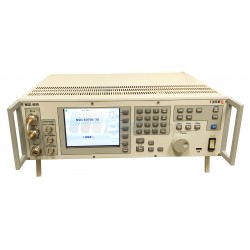
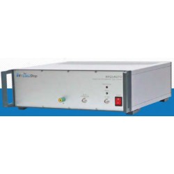
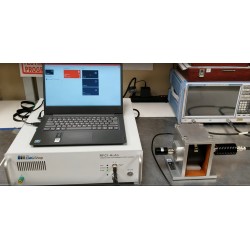
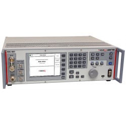
- RF generator with built in amp
- Laptop and control software
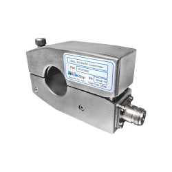
- BCI probe
- Calibration fixtures
- 100 Ohm Pasthrough
- RF Current monitor
- Attenuator Set
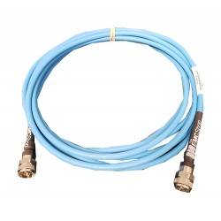
- RF Cable Set
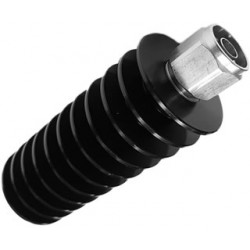
- Termination
- Manual
- Quick Start Guide
- Calibration Certificate
Video: Calibration to 10V - Bulk Current Injection
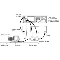
Overview of BCI Test Setup
When using clamp injection, the AE setup shall present the common mode impedance as
required in 6.2.1 as closely as possible (see Annex H). Each AE used with clamp injection
shall represent the functional installation conditions as closely as possible. To approximate
the required common mode impedance the following measures need to be taken.
– Each AE, used with clamp injection, shall be placed on an insulating support 0,1 m above
the reference ground plane.
– The clamp shall be placed on the cable to be tested. The clamp shall be supplied with the
test generator level previously established during the level setting procedure.
– During a test, a ground connection shall be made from the screen of the input port of the
current injection clamp or from the earth bar of the EM clamp, to the reference ground
plane (see Figures 14 and 15).
– A decoupling network shall be installed on each cable between the EUT and AE except
the cable under test.
– All cables connected to each AE, other than those being connected to the EUT, shall be
provided with decoupling networks, see 6.2.5 and Figure 5.
– The decoupling networks connected to each AE (except those on cables between the EUT
and AE) shall be applied no further than 0,3 m from the AE (distance: L2). The cable(s)
between the AE and the decoupling network(s) or in between the AE and the injection
clamp shall not be bundled nor wrapped and shall be kept at a height of 30 mm or more
above the reference ground plane (Figure 5).
– At one end of the cable under test is the EUT, and at the opposite end is the AE. Multiple
CDNs can be connected to the EUT and to the AE; however, only one CDN on each of the
EUT and AE shall be terminated in 50 :. The termination of the CDN shall be chosen
according to the priority in 7.5.
– When several clamps are used, the injection is carried out on each cable selected for
testing one by one. The cables which are selected for testing with the injection clamp but
not actually exercised shall be decoupled in accordance with 6.2.5.
When using clamp injection, and the common mode impedance requirements cannot be met at the AE side, it is necessary that the common mode impedance of the AE be less than or equal to the common mode impedance of the EUT port being tested. If not, measures shall be taken (e.g. by using a CDN-M1 or 150 : resistor from the AE to ground) at the AE port to satisfy this condition and to prevent resonances. In this procedure, only the relevant differences with those measures mentioned in 7.6 are given.
– Each AE and EUT used with clamp injection shall represent the functional installation
conditions as closely as possible, e.g. the EUT shall either be connected to the reference
ground plane or placed on an insulating support (see Figures 14 and 15).
– By means of a current monitoring probe (having low insertion loss), inserted in between
the injection clamp and the EUT, the current resulting from the induced voltage (set
according to 6.4.1) shall be monitored. If the current exceeds the nominal circuit value
Imax given below, the test generator level shall be reduced until the measured current is
equal to the Imax value:
Associated EMC Test Equipment
16 other products in the same category:
-
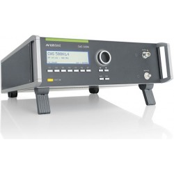
Teseq NSG 4070C-35 Test System for Conducted RF Immunity to IEC 61000-4-6
-
RFCI-Auto Conducted Immunity Test System for ISO 11452-4
-
Amplifier Research CI00400AM4 BCI RF Conducted Immunity Generator
-

ETT Copper EMC Test Table
-
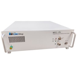
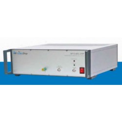
RFCI-75 RF Conducted Immunity Generator, 100 kHz - 400 MHz
-
Bulk Current Injection Test Setup - 400mA Automotive
-
RFCI-MIL RF Conducted Susceptibility Generator for BCI Testing
-
Teseq NSG 4070B Conducted & Radiated Immunity Test System
-
Narda PMM COND-IS/10 RF Conductive Immunity Test System
-
ISO 11452-4 Turn Key Solution for Harness Excitation Methods (BCI and TWC)
-
SS250M-500, 10 kHz to 250 MHz RF Amplifier, 500 Watt
-

Rent Teseq NSG 4070C-45 Test System for Conducted & Radiated Immunity
-
Teseq NSG 4031 Broadband Immunity Test System for IEC 61000-4-31
-
Em Test CWS 500N1.4 RF Conducted Immunity Test System for IEC 61000-4-6
-
Rent Turnkey RF Conductive Immunity Test System per IEC 61000-4-6
-
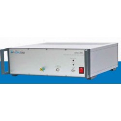
RFCI-IEC-25 RF Conducted Immunity Test System