
No products
Product successfully added to your shopping cart
There are 0 items in your cart. There is 1 item in your cart.
Loop Antennas
- EMC Test Equipment
- Transient Generators
- RF Power Amplifiers
- DC - 300 kHz RF Amplifiers
- 10 kHz - 250 MHz RF Amplifiers
- 10 kHz - 400 MHz RF Amplifiers
- 10 kHz - 1 GHz RF Amplifiers
- 80 MHz - 1 GHz RF Amplifiers
- 1 GHz - 2 GHz RF Amplifiers
- 700 MHz - 4.2 GHz RF Amplifiers
- 1 GHz - 6 GHz RF Amplifiers
- 2 GHz - 8 GHz RF Amplifiers
- 6 GHz - 18 GHz RF Amplifiers
- 18 GHz - 40 GHz RF Amplifiers
- Pulse Amplifiers
- RF Field Strength Probes & Meters
- RF Conducted Immunity
- EMC Receivers/EMI Analyzers
- EMC Antennas
- Coupling Decoupling Networks (CDN's)
- Line Impedance Stabilization Networks (LISN's)
- RF Test Equipment
- EMC Probes
- EMC Measurement & Equipment Software
- Power Supplies
- Electrical Safety Analyzers
- High Precision Laboratory Power Analyzers & Meters
- Anechoic Chambers
- Over-the-Air (OTA) Test Chambers
- EMI RF Shielded Tent Enclosures
- RF Shielded Rooms
- EMC Absorber
- Positioning Equipment
- EMC/EMI Test Setup
- GTEM Cells / TEM Cells
- Reverberation Chambers
- Used RF Anechoic Chambers
- EMC Chamber Filters
- EMC Chamber Shielding Gaskets
- RF Shielded Doors
- Anechoic Chamber Accessories
- Fully Anechoic (FAR) Test Chambers
- Manufacturers
- 3ctest
- AE Techron
- AH Systems
- Amplifier Research
- Boonton
- Com-Power
- Diamond Engineering
- EM Test (Ametek CTS)
- EMC Partner
- EMC Test Design
- Empower High Power RF Amplifiers
- ETS-lindgren
- Log Periodic Dipole Array Antenna
- Near Field Probe Sets
- Double Ridge Horn Antennas
- Biconical Antennas
- Quad Ridge Horn Antennas
- Electric Field Probes
- GTEM's
- Positioners & Tripods
- Loop Antennas
- Biconilog Antennas
- LISN's (Line Impedance Stabilization Network)
- Shielded Enclosures/Rooms
- Monopole Antennas
- Field Generating Antennas
- Fischer Custom Communications
- Haefely Hipotronics
- Haefely EFT/Burst Immunity Test Systems
- Haefely Surge Combination Wave Test Systems
- Haefely Surge Damped Oscillating Wave Test Systems
- Haefely Electrostatic Discharge Test Systems (ESD)
- Haefely Surge Ring Wave Test Systems
- Haefely Surge Telecom Wave Test Systems
- Haefely Magnetic Field Test Systems
- Haefely CDN's (Coupling/Decoupling Networks)
- IFI Amplifiers
- Keysight (Agilent)
- MVG - Microwave Vision Group
- PMM / Narda
- Rohde & Schwarz RF Test Equipment
- Rohde & Schwarz Broadband RF Amplifiers
- Rohde & Schwarz Spectrum Analyzers
- Rohde & Schwarz Compliant EMI Test Receivers
- Rohde & Schwarz Isotropic RF Probes
- Rohde & Schwarz RF Signal Generators
- Rohde & Schwarz RF Switches
- Rohde & Schwarz Oscilloscopes
- Rohde & Schwarz RF Power Meters
- Rohde & Schwarz RF Power Sensors
- Schloder
- Schwarzbeck Mess-Elektronik
- Schwarzbeck Antennas
- Schwarzbeck Automotive Antennas
- Schwarzbeck Broadband Horn Antennas
- Schwarzbeck Biconical Antennas
- Schwarzbeck Logarithmic Periodic Broadband Antennas
- Schwarzbeck Stacked Log-Periodic Broadband Antennas
- Schwarzbeck Biconic Log-Periodic Antennas
- Schwarzbeck Dipole Antennas
- Schwarzbeck Rod Antennas
- Schwarbeck Antenna Baluns / Holders
- Schwarzbeck LISN Line Impedance Stabilisation Networks
- Schwarbeck Decoupling & Absorbing Clamps
- Schwarzbeck Field Probes
- Schwarzbeck Helmholtz Coils
- Schwarzbeck Antenna Masts
- Schwarzbeck Coupling/Decoupling Networks
- Schwarzbeck Antennas
- Solar Electronics
- Teseq (Schaffner)
- Teseq Automotive Transient Generators
- Teseq RF Test Equipment
- Teseq EFT/Burst Generators
- Teseq RF Immunity Generators
- Teseq ESD Guns
- Teseq Surge Generators
- Teseq Harmonics & Flicker Solutions
- Teseq Dips, Interrupts & Variations Equipment
- Teseq Ring Wave Generators
- Teseq Oscillatory Waves Generators
- Teseq Absorbing Clamps / Ferrite Tube
- Teseq EMC Antennas
- Teseq Current Probes
- Teseq Coupling Networks
- Thermo Keytek
- Vicreate
- Compliance Standards
- International (IEC/EN)
- EN/IEC 61000-3-2
- EN/IEC 61000-3-3
- IEC 61000-3-11
- IEC / EN 610000-3-12
- EN/IEC 61000-4-2
- EN/IEC 61000-4-3
- EN/IEC 61000-4-4
- EN/IEC 61000-4-5
- EN/IEC 61000-4-6
- EN/IEC 61000-4-7
- EN/IEC 61000-4-8
- EN/IEC 61000-4-9
- EN/IEC 61000-4-10
- EN/IEC 61000-4-11
- EN/IEC 61000-4-12
- EN/IEC 61000-4-16
- EN/IEC 61000-4-18
- EN/IEC 61000-4-19
- EN/IEC 61000-4-20
- EN/IEC 61000-4-21
- EN/IEC 61000-4-29
- EN/IEC 61000-4-31
- IEC 61000-4-39
- EN/IEC 62132
- SEMI F47 Voltage Sag Immunity
- Product Standards
- Military & Aerospace Standards
- Automotive EMC Standards
- CISPR Standards
- Telecom Testing
- ANSI/IEEE Standards
- FCC Part 15
- FCC Part 30
- International (IEC/EN)
- Application/Test Type
- Radiated Immunity
- Bulk Current Injection Testing
- RF Emissions Testing
- Conducted Immunity
- Conducted Emissions
- Antenna Pattern Measurement
- CE Mark Testing
- Intentional Radiator Testing
- Pulsed HIRF Radar
- Over-the-Air (OTA) Testing
- 5G Test Solutions
- Automotive EMC
- SAR Measurement Equipment
- Radiated Emissions
- Battery Simulator Test Equipment
- Services
- Clearance
Viewed products
-

Schwarzbeck FMZB 1512...
9 kHz - 30 MHz Frequency Range Active...
-

Langer EMV-Technik MP...
1 GHz Frequency Range Measuring...
 View larger
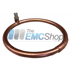
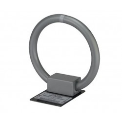
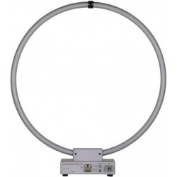
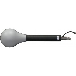
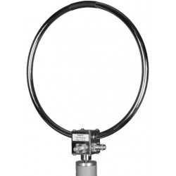
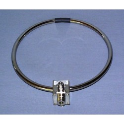
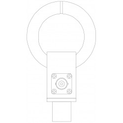
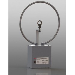
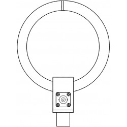
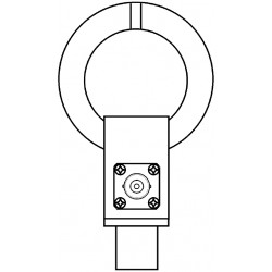
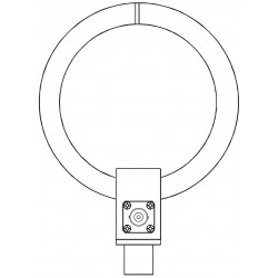
Schwarzbeck FMZB 1512 Active Handheld RX Loop Antenna
New
- 9 kHz - 30 MHz Frequency Range
- Active Receiving Loop Antenna
- Active shielded handheld loop antenna
- With nearly constant antenna factor over the entire frequency range
- It can be used for testing acording to CISPR, MIL, FCC, EN, ISO, ANSI, ETSI and many other standards
PDF Downloads
Test Equipment Description
The Schwarzbeck FMZB 1512 is an active, shielded handheld loop antenna with nearly constant antenna factor over the entire frequency range. It can be used for testing according to CISPR, MIL, FCC, EN, ISO, ANSI, ETSI and many other standards.
It can be used for the frequency selective measurement of magnetic fields (or fictive electric field) in the frequency range from 9 kHz to 30 MHz.
Since it is directional sensitive one can locate field sources.
| Schwarzbeck FMZB 1512 Specifications | |
| Nominal Frequency Range | 9 kHz - 30 MHz |
| Loop diameter | 150 mm |
| RF connector | N-Buchse 50 Ω N-female 50 Ω |
| Antenna factor for fict. E-fieldstrength | 20 dB/m |
| Antennna factor for H-fieldstrength | -31.5 dB/Ωm |
| Attenuator | 0 - 33 dB in 3 dB steps |
| Maximum field strength | (Switch kE ≥ 44 dB/m): 162 dBµV/m (126 V/m) 110.5 dBµA/m (0.33 A/m) |
| Frequency response | < ± 3 dB |
| Operation time with fully charged batteries | >12 h typ. 16 h |
| Battery capacity | NiMH 9.6 V / 800 mAh |
| Mount | 22 x 40 mm |
| Dimensions | 165 mm x 350 mm x 45 mm |
| Material | Aluminium |
| Weight | 500 g |
| Accessories | |
| NiMH-Charger | ACS 48 |
The active loop antenna is especially suitable for mobile applications, for instance if used with a handheld spectrum analyzer. Combined with a CISPR 16 EMI-receiver the FMZB 1512 makes a convenient field strength measuring system with low noise and pulse measuring capabilities.
Since the FMZB 1512 is a highly sensitive, light weight magnetic loop antenna it is particularly suited for the direction finding of signal and noise sources.
The FMZB 1512 is equipped with 8 NiMHMignon cells (AAA) to keep the weight as low as possible for mobile use. The battery voltage is indicated by a LED. A green light shows normal operation and a red light means that you have to recharge urgently. Although it is possible to measure while recharging, we do not recommend to do so because most NiMH chargers operate in pulsed mode and create unwanted disturbance.
The shielded housing comes with a tube of 22 mm in diameter so it can be mounted on tripods with commonly used mast adapters (i.e. the AA 9202).
Schwarzbeck FMZB 1512 Operation
The active loop antenna FMZB 1512 can be switched on with a toggle switch at the top side of the housing. Therefore the switch has to be put into the position “ON”.
After turning the device on the LED which is located left from the switch will be illuminated. When it is illuminated green, the battery is charged sufficiently. When the LED glows red, you have to charge it by all means. If there is no LED indication, the battery is totally discharged. Exhaustive discharging should be avoided in any case because the lifetime of batteries can suffer.
To charge the accumulators you have to connect the charger to the socket at the right side of the housing of the FMZB 1512. The charging time is typically 62 hours.
Avoid shorting the charging contacts! Protect from moisture!
The gain can be adjusted by the rotary switch. The maximum possible gain corresponds to an electric antenna factor of kE = 20 dB/m and can be decreased in 3 dB steps down to kE = 53 dB/m. Since the frequency response of FMZB 1512 varies slightly above 10 MHz when switching the attenuator, the recommended setting for accurate measurements is the switch position kE = 20 dB/m. The supplied calibration data refers also to the switch position kE = 20 dB/m.

The probe is directional sensitive. You can find the maximum level by turning the probe. The result depends on the frequency as well as on the distance to the signal source.
Sources of fields can be located.
Schwarzbeck FMZB 1512 Basics
In the near field of a radiation source electric and magnetic field components have to be examined separately. A common definition is a distance < λ/2π as near field. Keeping in mind that a frequency of 100 kHz corresponds to a wave length of 3 km (approx. 1.9 miles), usually measurements up to several megahertz can be considered to be near field measurements.
Schwarzbeck FMZB 1512 Construction
Magnetic field probes have to suppress electric fields as far as possible. This is achieved using an electric shielding of the loop (tube) which is disconnected in the middle to avoid a magnetic short circuit of the winding. Basic physics shows that the unloaded voltage of a loop is proportional to the frequency. Active probes overcome this problem by measuring the short circuit current of the loop.
Schwarzbeck FMZB 1512 Field strength range
FMZB 1512 are the best choice when small field strengths have to be measured. The lower limit is better than 1 µA/m. The maximum fieldstrength values of 126 V/m or 0.33 A/m can be measured using the switch positions kE ≥ 44 dB/m.
Magnetic probes and fictitious magnetic fieldstrength
The Loop antennas of the FMZB series will always and only measure magnetic field strength.
The undesired sensitivity for the electric field strength is considerably lowered using a loop shielding.
Nevertheless you can transform the “fictive” e-field strength by a value of +20 dB/m.
When far-fields are being measured, one has to add the conversion factor for e-fields (kE) in dBµV/m to the measured result of the receiver in dBµV.
This is based on the fact that in the far field of an antenna electric and magnetic field strength are related via the characteristic field impedance of the free space (377 Ω). The conversion from magnetic field strength to fictive electric field strength does not depend on the frequency and is 51.5 dB (=20lg(377Ω).
F [dBµV/m]=G [dBµA/m]+51.5 dB
F: Electric field strength-level
G: Magnetic field strength-level Z = 120 πΩ = 377 Ω
or:
E [V/m]=H [A/m] x 377Ω
E: Electric field strength
H: Magnetic field strength
| Internal noise of the probe (typ.) | ||
| F Receiver Fequency | Noise Level Voltage CISPR QP Det. BW 9 kHz | Noise Level Voltage Average Det. BW 200 Hz |
| 9 kHz | - | 30dBµV |
| 150 kHz | 32 dBµV | 10 dBµV |
| 1 MHz | 18 dBµV | -3 dBµV |
| 10 MHz | 15 dBµV | -7 dBµV |
| 30 MHz | 14 dBµV | -7 dBµV |

30 other products in the same category:
-
AH Systems SAS-560 Passive Loop Antenna for MIL-STD-461 RE 101
-
PLA30M-9K Passive Loop Antenna for CISPR, MIL-STD, ANSI C63.5 Compliance Testing
-
ETS Lindgren 7604 Magnetic Field Pickup Coil
-
Com-Power Model AL-130R Active Loop Antenna 9 kHz - 30 MHz
-
Solar Type 7334-1 Loop Sensor for RE01 and RE101 Magnetic Emission Tests
-
Teseq HLA 6121 60 cm Loop Antenna 9 kHz to 30 MHz
-
PMM (Narda) RF-300 Large Loop Antenna System (LLAS) for EN 55015 (CISPR - 15)
-
Solar Type 7429-1 Loop Antenna for RS01 Magnetic Field Tests
-
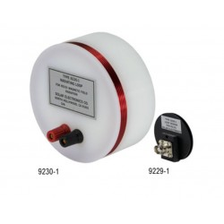
Solar Type 9230-1 Radiating Loop and Type 9229-1 Loop Sensor for MIL-STD-461D/RS101
-
Com-Power RS101 Loop Antenna Set for MIL-STD-461 RS101 Calibration & Test
-
EMCO 6511 Shielded Loop Antenna
-
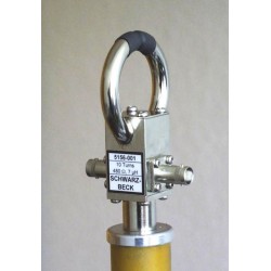
Schwarzbeck FMZB 1519 B Active Receive Loop Antenna
-
Schwarzbeck FSH3D Isotropic 3-Axial RX Loop Antenna
-
Schwarzbeck HFCD 9171 Calibration Balun
-
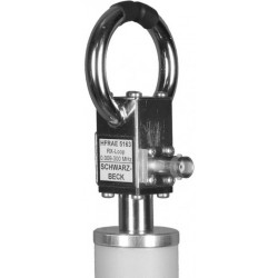
Schwarzbeck HFRA 1356 Passive Magnetic TX Loop Antenna
-
Schwarzbeck HFRA 5149 H-Field Transmit Loop VLF / HF
-

Schwarzbeck HFRA 5153 Transmit Loop Antenna For Calibrations
-
Schwarzbeck HFRA 5159 Transmit Loop Antenna
-

Schwarzbeck HFRA 5157 Transmit Loop Antenna For Calibrations
-
Schwarzbeck HFRA 5156 Transmit Loop Antenna For Calibrations
-
Schwarzbeck HFRAE 5163 Passive Magnetic RX Loop Antenna
-
Schwarzbeck HFRAE 5162 Passive Magnetic RX Loop Antenna
-

Schwarzbeck HFRAE 5161 Passive Magnetic RX Loop Antenna
-
Schwarzbeck HFRAE 5160 Passive RX-Loop Antenna
-
Schwarzbeck HFRA SF02G Passive Magnetic Transmitting Loop Antenna
-
Schwarzbeck HFRA 5170 Transmit Loop Antenna For Calibrations
-
Schwarzbeck HFRA 5155 Passive Magnetic TX Loop Antenna
-
Schwarzbeck HFRA 5154 Transmit Loop Antenna For Calibrations
-
Schwarzbeck HXYZ 9170 Triple Loop Antenna
-
Schwarzbeck HMDA 1545 Sensitive Magnetic Field-Strength Meter with LCD Reading