
No products
Product successfully added to your shopping cart
There are 0 items in your cart. There is 1 item in your cart.
Loop Antennas
- EMC Test Equipment
- Transient Generators
- RF Power Amplifiers
- DC - 300 kHz RF Amplifiers
- 10 kHz - 250 MHz RF Amplifiers
- 10 kHz - 400 MHz RF Amplifiers
- 10 kHz - 1 GHz RF Amplifiers
- 80 MHz - 1 GHz RF Amplifiers
- 1 GHz - 2 GHz RF Amplifiers
- 700 MHz - 4.2 GHz RF Amplifiers
- 1 GHz - 6 GHz RF Amplifiers
- 2 GHz - 8 GHz RF Amplifiers
- 6 GHz - 18 GHz RF Amplifiers
- 18 GHz - 40 GHz RF Amplifiers
- Pulse Amplifiers
- RF Field Strength Probes & Meters
- RF Conducted Immunity
- EMC Receivers/EMI Analyzers
- EMC Antennas
- Coupling Decoupling Networks (CDN's)
- Line Impedance Stabilization Networks (LISN's)
- RF Test Equipment
- EMC Probes
- EMC Measurement & Equipment Software
- Power Supplies
- Electrical Safety Analyzers
- High Precision Laboratory Power Analyzers & Meters
- Anechoic Chambers
- Over-the-Air (OTA) Test Chambers
- EMI RF Shielded Tent Enclosures
- RF Shielded Rooms
- EMC Absorber
- Positioning Equipment
- EMC/EMI Test Setup
- GTEM Cells / TEM Cells
- Reverberation Chambers
- Used RF Anechoic Chambers
- EMC Chamber Filters
- EMC Chamber Shielding Gaskets
- RF Shielded Doors
- Anechoic Chamber Accessories
- Fully Anechoic (FAR) Test Chambers
- Manufacturers
- 3ctest
- AE Techron
- AH Systems
- Amplifier Research
- Boonton
- Com-Power
- Diamond Engineering
- EM Test (Ametek CTS)
- EMC Partner
- EMC Test Design
- Empower High Power RF Amplifiers
- ETS-lindgren
- Log Periodic Dipole Array Antenna
- Near Field Probe Sets
- Double Ridge Horn Antennas
- Biconical Antennas
- Quad Ridge Horn Antennas
- Electric Field Probes
- GTEM's
- Positioners & Tripods
- Loop Antennas
- Biconilog Antennas
- LISN's (Line Impedance Stabilization Network)
- Shielded Enclosures/Rooms
- Monopole Antennas
- Field Generating Antennas
- Fischer Custom Communications
- Haefely Hipotronics
- Haefely EFT/Burst Immunity Test Systems
- Haefely Surge Combination Wave Test Systems
- Haefely Surge Damped Oscillating Wave Test Systems
- Haefely Electrostatic Discharge Test Systems (ESD)
- Haefely Surge Ring Wave Test Systems
- Haefely Surge Telecom Wave Test Systems
- Haefely Magnetic Field Test Systems
- Haefely CDN's (Coupling/Decoupling Networks)
- IFI Amplifiers
- Keysight (Agilent)
- MVG - Microwave Vision Group
- PMM / Narda
- Rohde & Schwarz RF Test Equipment
- Rohde & Schwarz Broadband RF Amplifiers
- Rohde & Schwarz Spectrum Analyzers
- Rohde & Schwarz Compliant EMI Test Receivers
- Rohde & Schwarz Isotropic RF Probes
- Rohde & Schwarz RF Signal Generators
- Rohde & Schwarz RF Switches
- Rohde & Schwarz Oscilloscopes
- Rohde & Schwarz RF Power Meters
- Rohde & Schwarz RF Power Sensors
- Schloder
- Schwarzbeck Mess-Elektronik
- Schwarzbeck Antennas
- Schwarzbeck Automotive Antennas
- Schwarzbeck Broadband Horn Antennas
- Schwarzbeck Biconical Antennas
- Schwarzbeck Logarithmic Periodic Broadband Antennas
- Schwarzbeck Stacked Log-Periodic Broadband Antennas
- Schwarzbeck Biconic Log-Periodic Antennas
- Schwarzbeck Dipole Antennas
- Schwarzbeck Rod Antennas
- Schwarbeck Antenna Baluns / Holders
- Schwarzbeck LISN Line Impedance Stabilisation Networks
- Schwarbeck Decoupling & Absorbing Clamps
- Schwarzbeck Field Probes
- Schwarzbeck Helmholtz Coils
- Schwarzbeck Antenna Masts
- Schwarzbeck Coupling/Decoupling Networks
- Schwarzbeck Antennas
- Solar Electronics
- Teseq (Schaffner)
- Teseq Automotive Transient Generators
- Teseq RF Test Equipment
- Teseq EFT/Burst Generators
- Teseq RF Immunity Generators
- Teseq ESD Guns
- Teseq Surge Generators
- Teseq Harmonics & Flicker Solutions
- Teseq Dips, Interrupts & Variations Equipment
- Teseq Ring Wave Generators
- Teseq Oscillatory Waves Generators
- Teseq Absorbing Clamps / Ferrite Tube
- Teseq EMC Antennas
- Teseq Current Probes
- Teseq Coupling Networks
- Thermo Keytek
- Vicreate
- Compliance Standards
- International (IEC/EN)
- EN/IEC 61000-3-2
- EN/IEC 61000-3-3
- IEC 61000-3-11
- IEC / EN 610000-3-12
- EN/IEC 61000-4-2
- EN/IEC 61000-4-3
- EN/IEC 61000-4-4
- EN/IEC 61000-4-5
- EN/IEC 61000-4-6
- EN/IEC 61000-4-7
- EN/IEC 61000-4-8
- EN/IEC 61000-4-9
- EN/IEC 61000-4-10
- EN/IEC 61000-4-11
- EN/IEC 61000-4-12
- EN/IEC 61000-4-16
- EN/IEC 61000-4-18
- EN/IEC 61000-4-19
- EN/IEC 61000-4-20
- EN/IEC 61000-4-21
- EN/IEC 61000-4-29
- EN/IEC 61000-4-31
- IEC 61000-4-39
- EN/IEC 62132
- SEMI F47 Voltage Sag Immunity
- Product Standards
- Military & Aerospace Standards
- Automotive EMC Standards
- CISPR Standards
- Telecom Testing
- ANSI/IEEE Standards
- FCC Part 15
- FCC Part 30
- International (IEC/EN)
- Application/Test Type
- Radiated Immunity
- Bulk Current Injection Testing
- RF Emissions Testing
- Conducted Immunity
- Conducted Emissions
- Antenna Pattern Measurement
- CE Mark Testing
- Intentional Radiator Testing
- Pulsed HIRF Radar
- Over-the-Air (OTA) Testing
- 5G Test Solutions
- Automotive EMC
- SAR Measurement Equipment
- Radiated Emissions
- Battery Simulator Test Equipment
- Services
- Clearance
Viewed products
-

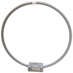
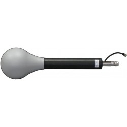
Schwarzbeck HMDA 1545...
9 kHz - 50 (80) MHz Handheld magnetic...
 View larger
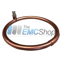
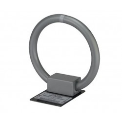
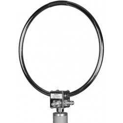
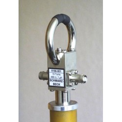
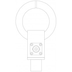
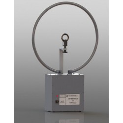
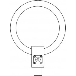
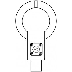
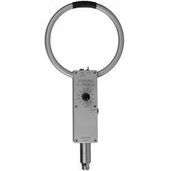
Schwarzbeck HMDA 1545 Sensitive Magnetic Field-Strength Meter with LCD Reading
New
- 9 kHz - 50 (80) MHz
- Handheld magnetic field meter LCD
- Acustic fieldstrength indication with tone generator
- 200µA/m - 1 A/m
- 6 x Type AA NiMH
PDF Downloads
Test Equipment Description
Unlike low sensitivity passive meters, this active meter with a lower detection threshold of <46 dBmA/m (200 mA/m) operates also in the range of low fieldstrength.
In the insensitive range magnetic field- strength up to more than 120 dBmA/m ( 1 A/m) is covered. When many strong signals are present, or frequencies are of interest, the HMDA 1545 can be used as an active magnetic probe (loop antenna). Just connect the r.f.-output to a receiver or spectrum analyser.
The built-in tone generator and loudspeaker convert field-strength into variable tone frequency. This is very useful for radio direction finding with final reading of the 3 1/2 digit LCD.
The full metal cabinet and the electrically shielded antenna are very rugged. Operation via 3 toggle-switches is very easy. The built-in NiMH rechargeable battery gives 30 hours of operation . The optional Automatic Charger will perfectly charge the battery independent of its previous state.
| Schwarzbeck HMDA 1545 Technical Data | |
| Range of magnetic Field-Strength | 120 dBmA/m in two ranges. |
| Range 120 dBmA/m | Saturation 123 dBmA/m typ. |
| Range 100 dBmA/m | Saturation 103 dBmA/m typ. |
| Frequency range | 9 kHz - 100 MHz |
| Indication (Read-out) | LCD 3 1/2- digits Digits 12,5 mm high |
| Accuracy | |
| Design frequency range | 30 kHz - 30 MHz |
| For Field Strength | 50 dBmA/m - 120 dBmA/m |
| Measurement uncertainty | +/- 1.5 dB, typ. +/- 1 dB |
| 9 kHz - 30 kHz | see calibration sheet and plots |
| 30 MHz - 100 MHz | see calibration sheet and plots |
| R.f - Output | G[dBmA/m]=U[dBmV]+10 dB (+30 dB) for Load Impedance of 50 W only (1), N-Connector |
| Narrow-band operation with EMI receiver | + / - 2 dB (10 dBmA/m - 50 dBmA/m) + level deviation |
| Tone Generator | |
| Generator Frequency | |
| No Field- strength | <50 Hz typ. |
| Full range | >1.5 kHz typ. |
| Speaker, A.f-Volume in 2 steps and OFF via toggle switch with three positions. | |
| Power supply | Built-in rechargeable battery (6xType AA NiMH-Cells). Operation 30 hours typ |
| Low Battery indication using first decimal point left on the LCD. Automatic Charger (Optional) ACS 410 (Ansmann) | |
| Charging time | 3 hours typ. |
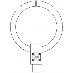
| Dimensions and Weight | |
| Loop diameter | 150 mm |
| Tube diameter | 12 mm |
| Main cabinet | 120x75x35mm |
| Handle with N-Connector | 140x22 mm |
| Weight | approx.. 1.5 kg |
| Full metal construction, chromium plated brass. (1) In order to save battery power, the output impedance of the R.f - Output is >50 Ohms. This leads to substantially higher voltage levels when high impedance measuring equipment (oscilloscopes) are in use. | |
1. Principle of Operation
A special operational amplifier using discrete components rather than integrated circuits converts the frequency independent loop-current caused by a magnetic field into a proportional voltage.
An r.-f.-attenuator can be switched between loop antenna and operational amplifier to get two amplitude ranges. This kind of switching results in improved measuring dynamic compared to switching at the end of the line by simply changing the DVM's sensitivity. The r.-f. output-voltage of the operational amplifier is fed to the input of a demodulating logarithmic amplifier. This amplifier provides a demodulated output proportional to the decibel value of the signal input over many decades. The dynamic range is in fact better than than that of the combination loop/operational amplifier, which is limited by internal noise and saturation effects.
The output voltage of the demodulating logarithmic amplifier controls the input of a digital volt-meter unit (DVM). The DVM shows the reading of magnetic field-strenght directly in dBmA/m. Furthermore the output voltage is converted into a variable audio frequency using a voltage to frequency converter which drives a small loudspeaker after further amplification. Increasing fieldstrength increases audio frequency. In contrast to the lcd-display, which is perfect for precise reading, the audio frequency information is fast and convenient.
Together with the directional behaviour of the loop, this feature makes direction finding of magnetic field sources easy. Magnetic field probes have to suppress electric fields as far as possible. This is accomplished using an electric shielding of the loop (tube) which is cut in the middle to avoid a magnetic short circuit of the winding.
2. Operation

2.1 Switch ON
Three toggle switches are located on the upper side of the metal box near the ending of the loop. Meter is ON in the left position of the toggle switch on the right side. The LCD-display is now active.
2.2 Switch Audio
The switch in the centre has three positions. Audio is off (mute) in the centre position. Left position is low, right position is loud audio.
The loudspeaker radiates a parasitic magnetic field of its own not far away from the loop antenna.
Under certain circumstances this may have negative influence on measurement. It is therefore good practice to switch off (mute) audio in the moment of LCD-reading whenever low fieldstrength levels are measured.
2.3 Switch Range
Switching Range will adapt the fieldstrength meter to the magnetic fieldstrength to be measured. In the right position the maximum fieldstrength to be measured is 100 dBmA/m, in the left 120 dBmA/m. There is a typical safety margin of 2 dB beyond these levels available, but it is good practice to switch to the higher range before the reading of 100 dBmA/m in lower range occurs. In the same way readings >120 dBmA/m in the higher range have to be considered as wrong.
For frequencies >30 MHz this margin is falling constantly. At 80 MHz saturation occurs 4.5 dB below full scale indication (see Appendix).
Inherent noise generated by the loop amplifier results in a basic reading, which is different in both ranges. This noise source is internal and must not be interpreted as external field-strength.
This reading is in fact the lower edge of indication.
2.4 LCD-display
The display has 3 1/2 digits. The MSD shows only "0" and "1". The unit of both ranges is [dBmA/m].
The decimal point on the right side of the MSD serves as an indicator for low battery.
When this decimal point is visible, the rechargeable NiMH-cells should be recharged.
Depending on many factors, there is a safety run-time of at least 15 minutes available.
Due to good internal voltage regulation and feedback techniques the meter will work even longer, but there is no guarantee for technical data under these circumstances.
2.5 Charging connector
The internal power supply of the meter uses six rechargeable NiMH-cells. When discharged, charging should be done with the automatic charger (option) ACS 410 (Ansmann). Combining NiMH-cells and automatic charger results in an optimum of operation time and lifetime expectation. You can even charge cells which are not completely discharged without side effects. Charging time for completely discharged cells is typically 3 hours.
2.6 R.-f.-output
The r.-f.-output may be connected to the input of a measuring receiver or spectrum analyser to monitor a frequency spectrum. In this way, radio broadcast transmitters can be identified according to their frequency.
The switchable range-attenuator is located at the input of the loop-amplifier. This means the conversion factor of the meter changes when ranges are changed.
| Range | Conversion factor |
| 100 dBmA/m | +10 dB |
| 120 dBmA/m | +30 dB |
In order to save battery power the r.-f.- output impedance is substantially higher than 50 ohms. This is no problem when measuring receivers or spectrum analysers with a 50 ohm input are in use. High impedance equipment such as oscilloscopes give a higher indication because of the insufficient load. A 50 ohm feed-through-terminator solves the problem.
As mentioned in 2.2, the loudspeaker may cause negative influence on measurement under certain circumstances. This is also true for the r.-f.-output. If problems occur switch off audio.
2.7 Loudspeaker
The loudspeaker is located behind the holes in the metal box. The volume is affected by 2.2.
3.1 Influence of internal noise
The noise of the amplifiers result in a basic (idle) reading, which is different in the two ranges, because the ranges are switched directly at the input i n front of these noise sources.
Because of the fact that the noise source is internal, it should not be considered as field-strength. In fact it must be considered as the lowest possible edge of measurement.
Measurement near this edge comes with a high error caused by noise. This error decreases with increasing signal/noise factor.
It is good practice to measure fieldstrength <90 dBmA/m always in the lower range, because internal noise is 20 dB lower than in the upper range, when the 20-dB-attenuator is between loop and loop amplifier.
3.2 Influence of saturation
Saturation of the loop amplifier is typically 2dB beyond upper range limit. When higher field-strength is applied, output voltage of the loop amplifier will not rise proportionally and clipping will occur.
If only one unmodulated signal at a time is present, considerations are quite simple.
If there are two or more strong amsignals present, as it is the case near a short wave transmitter area, these signals have to "share" the limited resources the loop amplifier. In this case for one single signal the upper range limit of 120 dBmA/m is no longer provided, but only a fraction.
The situation is even worse caused by the envelope of the am-modulated signals. Worst case consideration shows that there are moments, when all signals add up when they have maximum amplitude of the envelope.
Saturation has also negative effects considering receivers or spectrum analysers connected via the r.-f--output. In this case spurious signals occur, which are not present in the original (clean) spectrum. Due to the attenuator used in the upper range, intermodulation is lower, but noise is higher as explained in 3.1 (Low Noise-Low Distortion).
3.2.1 Influence of saturation >30 MHz
Up to 30 MHz saturation occurs beyond full scale of ranges.
At higher frequencies saturation restricts full scale indication. At 80 MHz, saturation occurs 4,5 dB below full scale of 120/100 dBmA/m. So be sure to switch to the higher range when you read 90 dBmA/m in the lower range. Saturation has no negative influence on smaller signals.
3.3 Frequency range
The frequency range is mainly limited by loop and loop amplifier. The loop amplifier has to load the loop with a very low impedance over a wide frequency range. Any component in this path, in this case the switchable attenuator, will cause some frequency dependent attenuation.
The frequency range is determined by a upper and lower limit. Within these limits the transducer factor is practically constant. In this case the frequency range is 50 kHz-80 MHz. Below the lower limit there is high-passcharacteristic, above the higher limit there is low-pass-characteristic.
As these characteristics are relatively smooth, field-strength outside this frequency range still gives a substantial reading. This reading may be used when the frequency is known and a correction table is used.
Furthermore, the attenuation of the switchable range-attenuator is optimised for the specified frequency range, not for outside frequencies.
Whenever field-strength with frequencies outside the specified frequency range is measured, or when the strongest of a couple of signals is outside the specified frequency range, there will be substantial differences when the ranges are changed.
A good example are computer-monitors. Their deflection coils radiate fields with frequencies near or outside the specified frequency range of the meter.
An example for signals above the specified frequency range are strong fm-transmitters in the range from 88 MHz-108 MHz.
30 other products in the same category:
-
AH Systems SAS-560 Passive Loop Antenna for MIL-STD-461 RE 101
-
PLA30M-9K Passive Loop Antenna for CISPR, MIL-STD, ANSI C63.5 Compliance Testing
-
ETS Lindgren 7604 Magnetic Field Pickup Coil
-
Com-Power Model AL-130R Active Loop Antenna 9 kHz - 30 MHz
-
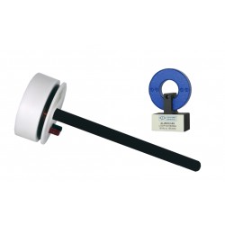
Solar Type 7334-1 Loop Sensor for RE01 and RE101 Magnetic Emission Tests
-
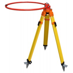
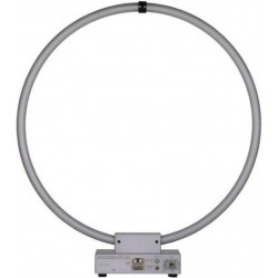
Teseq HLA 6121 60 cm Loop Antenna 9 kHz to 30 MHz
-
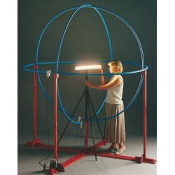
PMM (Narda) RF-300 Large Loop Antenna System (LLAS) for EN 55015 (CISPR - 15)
-
Solar Type 7429-1 Loop Antenna for RS01 Magnetic Field Tests
-
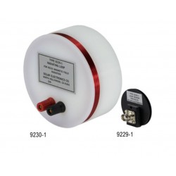
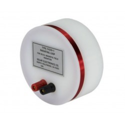
Solar Type 9230-1 Radiating Loop and Type 9229-1 Loop Sensor for MIL-STD-461D/RS101
-
Com-Power RS101 Loop Antenna Set for MIL-STD-461 RS101 Calibration & Test
-
EMCO 6511 Shielded Loop Antenna
-
Schwarzbeck FMZB 1519 B Active Receive Loop Antenna
-
Schwarzbeck FSH3D Isotropic 3-Axial RX Loop Antenna
-
Schwarzbeck HFCD 9171 Calibration Balun
-
Schwarzbeck HFRA 1356 Passive Magnetic TX Loop Antenna
-
Schwarzbeck HFRA 5149 H-Field Transmit Loop VLF / HF
-

Schwarzbeck HFRA 5153 Transmit Loop Antenna For Calibrations
-
Schwarzbeck HFRA 5159 Transmit Loop Antenna
-

Schwarzbeck HFRA 5157 Transmit Loop Antenna For Calibrations
-
Schwarzbeck HFRA 5156 Transmit Loop Antenna For Calibrations
-
Schwarzbeck HFRAE 5163 Passive Magnetic RX Loop Antenna
-
Schwarzbeck HFRAE 5162 Passive Magnetic RX Loop Antenna
-

Schwarzbeck HFRAE 5161 Passive Magnetic RX Loop Antenna
-
Schwarzbeck HFRAE 5160 Passive RX-Loop Antenna
-
Schwarzbeck HFRA SF02G Passive Magnetic Transmitting Loop Antenna
-
Schwarzbeck HFRA 5170 Transmit Loop Antenna For Calibrations
-
Schwarzbeck HFRA 5155 Passive Magnetic TX Loop Antenna
-
Schwarzbeck HFRA 5154 Transmit Loop Antenna For Calibrations
-
Schwarzbeck HXYZ 9170 Triple Loop Antenna
-
Schwarzbeck FMZB 1512 Active Handheld RX Loop Antenna