
No products
Product successfully added to your shopping cart
There are 0 items in your cart. There is 1 item in your cart.
Loop Antennas
- EMC Test Equipment
- Transient Generators
- RF Power Amplifiers
- DC - 300 kHz RF Amplifiers
- 10 kHz - 250 MHz RF Amplifiers
- 10 kHz - 400 MHz RF Amplifiers
- 10 kHz - 1 GHz RF Amplifiers
- 80 MHz - 1 GHz RF Amplifiers
- 1 GHz - 2 GHz RF Amplifiers
- 700 MHz - 4.2 GHz RF Amplifiers
- 1 GHz - 6 GHz RF Amplifiers
- 2 GHz - 8 GHz RF Amplifiers
- 6 GHz - 18 GHz RF Amplifiers
- 18 GHz - 40 GHz RF Amplifiers
- Pulse Amplifiers
- RF Field Strength Probes & Meters
- RF Conducted Immunity
- EMC Receivers/EMI Analyzers
- EMC Antennas
- Coupling Decoupling Networks (CDN's)
- Line Impedance Stabilization Networks (LISN's)
- RF Test Equipment
- EMC Probes
- EMC Measurement & Equipment Software
- Power Supplies
- Electrical Safety Analyzers
- High Precision Laboratory Power Analyzers & Meters
- Anechoic Chambers
- Over-the-Air (OTA) Test Chambers
- EMI RF Shielded Tent Enclosures
- RF Shielded Rooms
- EMC Absorber
- Positioning Equipment
- EMC/EMI Test Setup
- GTEM Cells / TEM Cells
- Reverberation Chambers
- Used RF Anechoic Chambers
- EMC Chamber Filters
- EMC Chamber Shielding Gaskets
- RF Shielded Doors
- Anechoic Chamber Accessories
- Fully Anechoic (FAR) Test Chambers
- Manufacturers
- 3ctest
- AE Techron
- AH Systems
- Amplifier Research
- Boonton
- Com-Power
- Diamond Engineering
- EM Test (Ametek CTS)
- EMC Partner
- EMC Test Design
- Empower High Power RF Amplifiers
- ETS-lindgren
- Log Periodic Dipole Array Antenna
- Near Field Probe Sets
- Double Ridge Horn Antennas
- Biconical Antennas
- Quad Ridge Horn Antennas
- Electric Field Probes
- GTEM's
- Positioners & Tripods
- Loop Antennas
- Biconilog Antennas
- LISN's (Line Impedance Stabilization Network)
- Shielded Enclosures/Rooms
- Monopole Antennas
- Field Generating Antennas
- Fischer Custom Communications
- Haefely Hipotronics
- Haefely EFT/Burst Immunity Test Systems
- Haefely Surge Combination Wave Test Systems
- Haefely Surge Damped Oscillating Wave Test Systems
- Haefely Electrostatic Discharge Test Systems (ESD)
- Haefely Surge Ring Wave Test Systems
- Haefely Surge Telecom Wave Test Systems
- Haefely Magnetic Field Test Systems
- Haefely CDN's (Coupling/Decoupling Networks)
- IFI Amplifiers
- Keysight (Agilent)
- MVG - Microwave Vision Group
- PMM / Narda
- Rohde & Schwarz RF Test Equipment
- Rohde & Schwarz Broadband RF Amplifiers
- Rohde & Schwarz Spectrum Analyzers
- Rohde & Schwarz Compliant EMI Test Receivers
- Rohde & Schwarz Isotropic RF Probes
- Rohde & Schwarz RF Signal Generators
- Rohde & Schwarz RF Switches
- Rohde & Schwarz Oscilloscopes
- Rohde & Schwarz RF Power Meters
- Rohde & Schwarz RF Power Sensors
- Schloder
- Schwarzbeck Mess-Elektronik
- Schwarzbeck Antennas
- Schwarzbeck Automotive Antennas
- Schwarzbeck Broadband Horn Antennas
- Schwarzbeck Biconical Antennas
- Schwarzbeck Logarithmic Periodic Broadband Antennas
- Schwarzbeck Stacked Log-Periodic Broadband Antennas
- Schwarzbeck Biconic Log-Periodic Antennas
- Schwarzbeck Dipole Antennas
- Schwarzbeck Rod Antennas
- Schwarbeck Antenna Baluns / Holders
- Schwarzbeck LISN Line Impedance Stabilisation Networks
- Schwarbeck Decoupling & Absorbing Clamps
- Schwarzbeck Field Probes
- Schwarzbeck Helmholtz Coils
- Schwarzbeck Antenna Masts
- Schwarzbeck Coupling/Decoupling Networks
- Schwarzbeck Antennas
- Solar Electronics
- Teseq (Schaffner)
- Teseq Automotive Transient Generators
- Teseq RF Test Equipment
- Teseq EFT/Burst Generators
- Teseq RF Immunity Generators
- Teseq ESD Guns
- Teseq Surge Generators
- Teseq Harmonics & Flicker Solutions
- Teseq Dips, Interrupts & Variations Equipment
- Teseq Ring Wave Generators
- Teseq Oscillatory Waves Generators
- Teseq Absorbing Clamps / Ferrite Tube
- Teseq EMC Antennas
- Teseq Current Probes
- Teseq Coupling Networks
- Thermo Keytek
- Vicreate
- Compliance Standards
- International (IEC/EN)
- EN/IEC 61000-3-2
- EN/IEC 61000-3-3
- IEC 61000-3-11
- IEC / EN 610000-3-12
- EN/IEC 61000-4-2
- EN/IEC 61000-4-3
- EN/IEC 61000-4-4
- EN/IEC 61000-4-5
- EN/IEC 61000-4-6
- EN/IEC 61000-4-7
- EN/IEC 61000-4-8
- EN/IEC 61000-4-9
- EN/IEC 61000-4-10
- EN/IEC 61000-4-11
- EN/IEC 61000-4-12
- EN/IEC 61000-4-16
- EN/IEC 61000-4-18
- EN/IEC 61000-4-19
- EN/IEC 61000-4-20
- EN/IEC 61000-4-21
- EN/IEC 61000-4-29
- EN/IEC 61000-4-31
- IEC 61000-4-39
- EN/IEC 62132
- SEMI F47 Voltage Sag Immunity
- Product Standards
- Military & Aerospace Standards
- Automotive EMC Standards
- CISPR Standards
- Telecom Testing
- ANSI/IEEE Standards
- FCC Part 15
- FCC Part 30
- International (IEC/EN)
- Application/Test Type
- Radiated Immunity
- Bulk Current Injection Testing
- RF Emissions Testing
- Conducted Immunity
- Conducted Emissions
- Antenna Pattern Measurement
- CE Mark Testing
- Intentional Radiator Testing
- Pulsed HIRF Radar
- Over-the-Air (OTA) Testing
- 5G Test Solutions
- Automotive EMC
- SAR Measurement Equipment
- Radiated Emissions
- Battery Simulator Test Equipment
- Services
- Clearance
Viewed products
-

Solar Type 7334-1 Loop...
for Test Method RE101 of...
 View larger
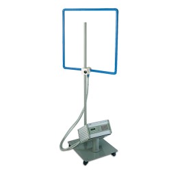
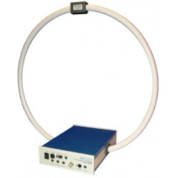
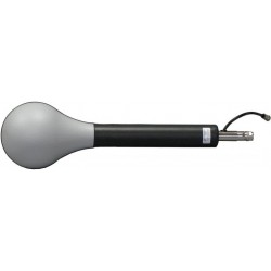
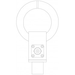
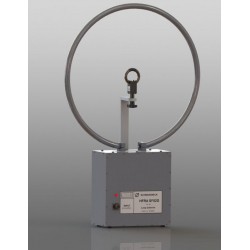
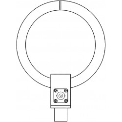
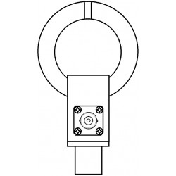
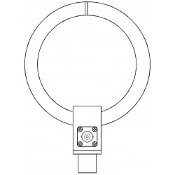
Solar Type 7334-1 Loop Sensor for RE01 and RE101 Magnetic Emission Tests
New
- for Test Method RE101 of MIL-STD-461F
- Required by Test Method RE01 in Parts 2 through 6 of MIL-STD- 461C and
- RE101 of MIL-STD-461D/E/F
Specifications
| Antennas Loop Antennas | |
| Parameter | Value |
| Connector | BNC |
| Construction | Shielding: Electrostatic |
| General Data Technical Details | |
| Parameter | Value |
| Dimensions | 5.24" diameter (13.3 cm) |
| Weight | 3 pounds (1.36 kg) |
Test Equipment Description
HISTORICAL NOTE
The AT-205/URM-6 loop sensor described in Test Method RE01 of MIL-STD-462 is one of the antennas designed for use with the Navy AN/URM-6B and Stoddart NM-10A receivers. These were the low frequency EMI meters that, in 1948, initiated the emphasis on EMI by the military departments and created the technical discipline we now know as Electromagnetic Compatibility.
DESCRIPTION
The Solar Type 7334-1 Loop Antenna was originally designed as a substitute for the AT-205/URM-6 antenna and is a replacement for Eaton Model 94607-1 as specified in RE01 of MIL-STD-461A. It continues to be used for Test Method RE101 of MIL-STD-461F.
The Type 7334-1 Loop Antenna is equipped with an epoxy-glass base plate which serves as a spacer to enable the user to place the loop at exactly 7 cm from the face of the item under test as required by Test Method RE101 of MIL-STD-461F.
APPLICATION
Connection to the loop is through a BNC connector which enables coaxial cabling to the EMI receiver. The loop is supplied with a correction factor graph (see Figures tab) showing the values in dB which must be added to the reading of a 50 Ω EMI meter to obtain answers in either dB/µV/m or dB/pT. The correction factor decreases as frequency increases from 30 Hz up to approximately 15 kHz, where the factor levels off and remains relatively constant up to 5 MHz.
The Type 7334-1 is required by Test Method RE01 in Parts 2 through 6 of MIL-STD-461C and RE101 of MIL-STD-461D/E/F. These portions of the specification require magnetic field emission tests of cables, equipments, systems and sub-systems installed in, or used in, all phases of military vehicles, ships, submarines, aircraft (including helicopters), spacecraft, or ground-based operations.
TEST METHODS RE01 and RE101
The Type 7334-1 is positioned 7 cm from the face of the equipment under test with the plane of the loop parallel to the equipment face. The best position to begin with is opposite or near a joint or seam.
The associated EMI receiver is then scanned over the range 30 Hz to 100 kHz searching for emissions. At the frequencies where emissions are found, the loop antenna is moved about the surface seeking the strongest emission level. When a strong signal is detected, the loop is oriented on its axis for a maximum reading.
This procedure is repeated for all surfaces of the equipment under test. Although the specification is not clear on the point, it appears to indicate that all six sides (including the bottom) of a piece of equipment must be tested in this manner.
When testing cables, the loop antenna is placed 7 cm from the cable with the plane of the loop parallel to the cable. The nonmetallic base plate of the Type 7334-1 provides a convenient means for establishing the correct 7 cm distance.
Dimensions: 5.24" diameter (13.3 cm)
Connector: BNC
Number of turns: 36
Wire: DC resistance between 5 and 10 Ω
Shielding: Electrostatic
Weight: 2 pounds (0.9 kg)
Shipping weight: 3 pounds (1.36 kg)

Associated EMC Test Equipment
30 other products in the same category:
-
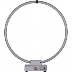
AH Systems SAS-560 Passive Loop Antenna for MIL-STD-461 RE 101
-
PLA30M-9K Passive Loop Antenna for CISPR, MIL-STD, ANSI C63.5 Compliance Testing
-
ETS Lindgren 7604 Magnetic Field Pickup Coil
-
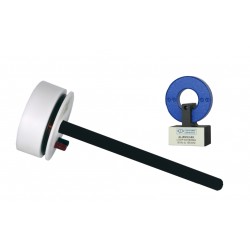
Com-Power Model AL-130R Active Loop Antenna 9 kHz - 30 MHz
-
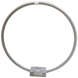
Teseq HLA 6121 60 cm Loop Antenna 9 kHz to 30 MHz
-
PMM (Narda) RF-300 Large Loop Antenna System (LLAS) for EN 55015 (CISPR - 15)
-
Solar Type 7429-1 Loop Antenna for RS01 Magnetic Field Tests
-
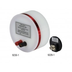
Solar Type 9230-1 Radiating Loop and Type 9229-1 Loop Sensor for MIL-STD-461D/RS101
-
Com-Power RS101 Loop Antenna Set for MIL-STD-461 RS101 Calibration & Test
-
EMCO 6511 Shielded Loop Antenna
-
Schwarzbeck FMZB 1519 B Active Receive Loop Antenna
-
Schwarzbeck FSH3D Isotropic 3-Axial RX Loop Antenna
-
Schwarzbeck HFCD 9171 Calibration Balun
-
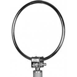
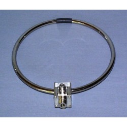
Schwarzbeck HFRA 1356 Passive Magnetic TX Loop Antenna
-
Schwarzbeck HFRA 5149 H-Field Transmit Loop VLF / HF
-

Schwarzbeck HFRA 5153 Transmit Loop Antenna For Calibrations
-
Schwarzbeck HFRA 5159 Transmit Loop Antenna
-

Schwarzbeck HFRA 5157 Transmit Loop Antenna For Calibrations
-
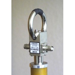
Schwarzbeck HFRA 5156 Transmit Loop Antenna For Calibrations
-
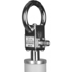
Schwarzbeck HFRAE 5163 Passive Magnetic RX Loop Antenna
-
Schwarzbeck HFRAE 5162 Passive Magnetic RX Loop Antenna
-

Schwarzbeck HFRAE 5161 Passive Magnetic RX Loop Antenna
-
Schwarzbeck HFRAE 5160 Passive RX-Loop Antenna
-
Schwarzbeck HFRA SF02G Passive Magnetic Transmitting Loop Antenna
-
Schwarzbeck HFRA 5170 Transmit Loop Antenna For Calibrations
-
Schwarzbeck HFRA 5155 Passive Magnetic TX Loop Antenna
-
Schwarzbeck HFRA 5154 Transmit Loop Antenna For Calibrations
-
Schwarzbeck HXYZ 9170 Triple Loop Antenna
-
Schwarzbeck FMZB 1512 Active Handheld RX Loop Antenna
-
Schwarzbeck HMDA 1545 Sensitive Magnetic Field-Strength Meter with LCD Reading