
No products
Product successfully added to your shopping cart
There are 0 items in your cart. There is 1 item in your cart.
Schwarzbeck Field Probes
- EMC Test Equipment
- Transient Generators
- RF Power Amplifiers
- DC - 300 kHz RF Amplifiers
- 10 kHz - 250 MHz RF Amplifiers
- 10 kHz - 400 MHz RF Amplifiers
- 10 kHz - 1 GHz RF Amplifiers
- 80 MHz - 1 GHz RF Amplifiers
- 1 GHz - 2 GHz RF Amplifiers
- 700 MHz - 4.2 GHz RF Amplifiers
- 1 GHz - 6 GHz RF Amplifiers
- 2 GHz - 8 GHz RF Amplifiers
- 6 GHz - 18 GHz RF Amplifiers
- 18 GHz - 40 GHz RF Amplifiers
- Pulse Amplifiers
- RF Field Strength Probes & Meters
- RF Conducted Immunity
- EMC Receivers/EMI Analyzers
- EMC Antennas
- Coupling Decoupling Networks (CDN's)
- Line Impedance Stabilization Networks (LISN's)
- RF Test Equipment
- EMC Probes
- EMC Measurement & Equipment Software
- Power Supplies
- Electrical Safety Analyzers
- High Precision Laboratory Power Analyzers & Meters
- Anechoic Chambers
- Over-the-Air (OTA) Test Chambers
- EMI RF Shielded Tent Enclosures
- RF Shielded Rooms
- EMC Absorber
- Positioning Equipment
- EMC/EMI Test Setup
- GTEM Cells / TEM Cells
- Reverberation Chambers
- Used RF Anechoic Chambers
- EMC Chamber Filters
- EMC Chamber Shielding Gaskets
- RF Shielded Doors
- Anechoic Chamber Accessories
- Fully Anechoic (FAR) Test Chambers
- Manufacturers
- 3ctest
- AE Techron
- AH Systems
- Amplifier Research
- Boonton
- Com-Power
- Diamond Engineering
- EM Test (Ametek CTS)
- EMC Partner
- EMC Test Design
- Empower High Power RF Amplifiers
- ETS-lindgren
- Log Periodic Dipole Array Antenna
- Near Field Probe Sets
- Double Ridge Horn Antennas
- Biconical Antennas
- Quad Ridge Horn Antennas
- Electric Field Probes
- GTEM's
- Positioners & Tripods
- Loop Antennas
- Biconilog Antennas
- LISN's (Line Impedance Stabilization Network)
- Shielded Enclosures/Rooms
- Monopole Antennas
- Field Generating Antennas
- Fischer Custom Communications
- Haefely Hipotronics
- Haefely EFT/Burst Immunity Test Systems
- Haefely Surge Combination Wave Test Systems
- Haefely Surge Damped Oscillating Wave Test Systems
- Haefely Electrostatic Discharge Test Systems (ESD)
- Haefely Surge Ring Wave Test Systems
- Haefely Surge Telecom Wave Test Systems
- Haefely Magnetic Field Test Systems
- Haefely CDN's (Coupling/Decoupling Networks)
- IFI Amplifiers
- Keysight (Agilent)
- MVG - Microwave Vision Group
- PMM / Narda
- Rohde & Schwarz RF Test Equipment
- Rohde & Schwarz Broadband RF Amplifiers
- Rohde & Schwarz Spectrum Analyzers
- Rohde & Schwarz Compliant EMI Test Receivers
- Rohde & Schwarz Isotropic RF Probes
- Rohde & Schwarz RF Signal Generators
- Rohde & Schwarz RF Switches
- Rohde & Schwarz Oscilloscopes
- Rohde & Schwarz RF Power Meters
- Rohde & Schwarz RF Power Sensors
- Schloder
- Schwarzbeck Mess-Elektronik
- Schwarzbeck Antennas
- Schwarzbeck Automotive Antennas
- Schwarzbeck Broadband Horn Antennas
- Schwarzbeck Biconical Antennas
- Schwarzbeck Logarithmic Periodic Broadband Antennas
- Schwarzbeck Stacked Log-Periodic Broadband Antennas
- Schwarzbeck Biconic Log-Periodic Antennas
- Schwarzbeck Dipole Antennas
- Schwarzbeck Rod Antennas
- Schwarbeck Antenna Baluns / Holders
- Schwarzbeck LISN Line Impedance Stabilisation Networks
- Schwarbeck Decoupling & Absorbing Clamps
- Schwarzbeck Field Probes
- Schwarzbeck Helmholtz Coils
- Schwarzbeck Antenna Masts
- Schwarzbeck Coupling/Decoupling Networks
- Schwarzbeck Antennas
- Solar Electronics
- Teseq (Schaffner)
- Teseq Automotive Transient Generators
- Teseq RF Test Equipment
- Teseq EFT/Burst Generators
- Teseq RF Immunity Generators
- Teseq ESD Guns
- Teseq Surge Generators
- Teseq Harmonics & Flicker Solutions
- Teseq Dips, Interrupts & Variations Equipment
- Teseq Ring Wave Generators
- Teseq Oscillatory Waves Generators
- Teseq Absorbing Clamps / Ferrite Tube
- Teseq EMC Antennas
- Teseq Current Probes
- Teseq Coupling Networks
- Thermo Keytek
- Vicreate
- Compliance Standards
- International (IEC/EN)
- EN/IEC 61000-3-2
- EN/IEC 61000-3-3
- IEC 61000-3-11
- IEC / EN 610000-3-12
- EN/IEC 61000-4-2
- EN/IEC 61000-4-3
- EN/IEC 61000-4-4
- EN/IEC 61000-4-5
- EN/IEC 61000-4-6
- EN/IEC 61000-4-7
- EN/IEC 61000-4-8
- EN/IEC 61000-4-9
- EN/IEC 61000-4-10
- EN/IEC 61000-4-11
- EN/IEC 61000-4-12
- EN/IEC 61000-4-16
- EN/IEC 61000-4-18
- EN/IEC 61000-4-19
- EN/IEC 61000-4-20
- EN/IEC 61000-4-21
- EN/IEC 61000-4-29
- EN/IEC 61000-4-31
- IEC 61000-4-39
- EN/IEC 62132
- SEMI F47 Voltage Sag Immunity
- Product Standards
- Military & Aerospace Standards
- Automotive EMC Standards
- CISPR Standards
- Telecom Testing
- ANSI/IEEE Standards
- FCC Part 15
- FCC Part 30
- International (IEC/EN)
- Application/Test Type
- Radiated Immunity
- Bulk Current Injection Testing
- RF Emissions Testing
- Conducted Immunity
- Conducted Emissions
- Antenna Pattern Measurement
- CE Mark Testing
- Intentional Radiator Testing
- Pulsed HIRF Radar
- Over-the-Air (OTA) Testing
- 5G Test Solutions
- Automotive EMC
- SAR Measurement Equipment
- Radiated Emissions
- Battery Simulator Test Equipment
- Services
- Clearance
Viewed products
-

Schwarzbeck CMDM 8700...
9 kHz – 30 MHz Frequency Measurement...
-

3ctest INS-40A /...
With Japanese technology...
 View larger
Schwarzbeck CMDM 8700 Common Mode / Differential Mode Switch
New
- 9 kHz – 30 MHz Frequency
- Measurement modes: Line A, Line B, Common mode, Differential mode
- Connectors: BNC (50 Ohm)
PDF Downloads
Test Equipment Description
The measurement mode switch CMDM 8700 expands the measurement possibilities of two V-LISN to T- and Delta-LISNs for the profound analysis of interference emissions.
You can measure the signals in four different ways:
- “Line A”
- “Line B”
- “Common Mode”
- “Differential Mode”
If the mode switch is set to “Line A” or “Line B” the unsymmetrical signals of the inputs A or B will be measured directly. The line which is not used at the moment will be terminated with 50 Ω internally. (V-LISN)
If the switch is set to the position "Common Mode" the common asymmetrical components of both inputs will be measured. (T- , Delta-LISN)
If the switch is set to "Differential Mode" the CDMD 8700 extracts the symmetrical components (common mode voltage) and routes them to the measurement output. (Delta-LISN)

Fig. 1. LISN Topologies
To protect the measurement receiver from low frequency interferences (below 7 kHz) there is a built-in high pass filter at the output. Measurements using the different operation modes allow to find the source of interference easier and to take steps to eliminate them. As for instance to suppress conducted common mode interferences common-mode chokes are used and bypass capacitors are connected to ground. When differential mode interferences occur you need to connect capacitors between the lines.

Fig. 2. Schematic circuit diagram of the CMDM 8700

Fig. 3. Typical measurement Setup

Fig. 4. Transmission of the inputs A and B
to OUTPUT using different modes

Fig. 5. Attenuation of symmetrical signals in common mode
and asymmetrical signals in differential mode

Fig. 6. Attenuation of unsymmetrical signals from A or B to OUTPUT in common mode.
The input that is not used is terminated with 50 Ω.
| Specifications | |
| Frequency range | 9 kHz – 30 MHz |
| Connectors | BNC |
| Impedance of Line A, Line B and output port | 50 Ω |
| Voltage division factor at the measuring port | (0 … - 2) dB |
| Material | Aluminium |
| Dimensions (housing W x H x D) | 105 x 49 x 120 mm |
| Weight | 490 g |
13 other products in the same category:
-
Schwarzbeck TK 9420 High Voltage Probe
-
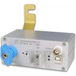
Schwarzbeck CP 9610 Current Probe 40A DC - 1 MHz
-
Schwarzbeck CVP 9222 B High Impedance Capacitive Voltage Probe
-
Schwarzbeck CAL 9222 Calibration Jig for Capacitive Voltage Probe CVP 9222
-
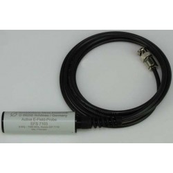
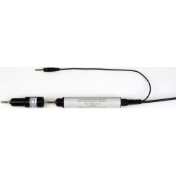
Schwarzbeck EFS 7103 Active Electric Field Probe
-
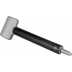
Schwarzbeck EFS 9218 Active Electric Field Probe
-
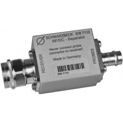
Schwarzbeck EW 7110 DC Separator
-
Schwarzbeck FSHPE Single Axis E-Field Antenna
-
Schwarzbeck FSHPH Single Axis H-Field Antenna
-
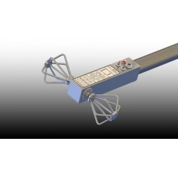
Schwarzbeck FSE3D Isotropic 3-axial RX Antenna
-
Schwarzbeck FMZB 1512 Active Handheld RX Loop Antenna
-
Schwarzbeck HMDA 1545 Sensitive Magnetic Field-Strength Meter with LCD Reading
-
Schwarzbeck HFS 1546 Active Magnetic Field Probe with Electrically Shielded Loop