
No products
Product successfully added to your shopping cart
There are 0 items in your cart. There is 1 item in your cart.
Schwarzbeck Field Probes
- EMC Test Equipment
- Transient Generators
- RF Power Amplifiers
- DC - 300 kHz RF Amplifiers
- 10 kHz - 250 MHz RF Amplifiers
- 10 kHz - 400 MHz RF Amplifiers
- 10 kHz - 1 GHz RF Amplifiers
- 80 MHz - 1 GHz RF Amplifiers
- 1 GHz - 2 GHz RF Amplifiers
- 700 MHz - 4.2 GHz RF Amplifiers
- 1 GHz - 6 GHz RF Amplifiers
- 2 GHz - 8 GHz RF Amplifiers
- 6 GHz - 18 GHz RF Amplifiers
- 18 GHz - 40 GHz RF Amplifiers
- Pulse Amplifiers
- RF Field Strength Probes & Meters
- RF Conducted Immunity
- EMC Receivers/EMI Analyzers
- EMC Antennas
- Coupling Decoupling Networks (CDN's)
- Line Impedance Stabilization Networks (LISN's)
- RF Test Equipment
- EMC Probes
- EMC Measurement & Equipment Software
- Power Supplies
- Electrical Safety Analyzers
- High Precision Laboratory Power Analyzers & Meters
- Anechoic Chambers
- Over-the-Air (OTA) Test Chambers
- EMI RF Shielded Tent Enclosures
- RF Shielded Rooms
- EMC Absorber
- Positioning Equipment
- EMC/EMI Test Setup
- GTEM Cells / TEM Cells
- Reverberation Chambers
- Used RF Anechoic Chambers
- EMC Chamber Filters
- EMC Chamber Shielding Gaskets
- RF Shielded Doors
- Anechoic Chamber Accessories
- Fully Anechoic (FAR) Test Chambers
- Manufacturers
- 3ctest
- AE Techron
- AH Systems
- Amplifier Research
- Boonton
- Com-Power
- Diamond Engineering
- EM Test (Ametek CTS)
- EMC Partner
- EMC Test Design
- Empower High Power RF Amplifiers
- ETS-lindgren
- Log Periodic Dipole Array Antenna
- Near Field Probe Sets
- Double Ridge Horn Antennas
- Biconical Antennas
- Quad Ridge Horn Antennas
- Electric Field Probes
- GTEM's
- Positioners & Tripods
- Loop Antennas
- Biconilog Antennas
- LISN's (Line Impedance Stabilization Network)
- Shielded Enclosures/Rooms
- Monopole Antennas
- Field Generating Antennas
- Fischer Custom Communications
- Haefely Hipotronics
- Haefely EFT/Burst Immunity Test Systems
- Haefely Surge Combination Wave Test Systems
- Haefely Surge Damped Oscillating Wave Test Systems
- Haefely Electrostatic Discharge Test Systems (ESD)
- Haefely Surge Ring Wave Test Systems
- Haefely Surge Telecom Wave Test Systems
- Haefely Magnetic Field Test Systems
- Haefely CDN's (Coupling/Decoupling Networks)
- IFI Amplifiers
- Keysight (Agilent)
- MVG - Microwave Vision Group
- PMM / Narda
- Rohde & Schwarz RF Test Equipment
- Rohde & Schwarz Broadband RF Amplifiers
- Rohde & Schwarz Spectrum Analyzers
- Rohde & Schwarz Compliant EMI Test Receivers
- Rohde & Schwarz Isotropic RF Probes
- Rohde & Schwarz RF Signal Generators
- Rohde & Schwarz RF Switches
- Rohde & Schwarz Oscilloscopes
- Rohde & Schwarz RF Power Meters
- Rohde & Schwarz RF Power Sensors
- Schloder
- Schwarzbeck Mess-Elektronik
- Schwarzbeck Antennas
- Schwarzbeck Automotive Antennas
- Schwarzbeck Broadband Horn Antennas
- Schwarzbeck Biconical Antennas
- Schwarzbeck Logarithmic Periodic Broadband Antennas
- Schwarzbeck Stacked Log-Periodic Broadband Antennas
- Schwarzbeck Biconic Log-Periodic Antennas
- Schwarzbeck Dipole Antennas
- Schwarzbeck Rod Antennas
- Schwarbeck Antenna Baluns / Holders
- Schwarzbeck LISN Line Impedance Stabilisation Networks
- Schwarbeck Decoupling & Absorbing Clamps
- Schwarzbeck Field Probes
- Schwarzbeck Helmholtz Coils
- Schwarzbeck Antenna Masts
- Schwarzbeck Coupling/Decoupling Networks
- Schwarzbeck Antennas
- Solar Electronics
- Teseq (Schaffner)
- Teseq Automotive Transient Generators
- Teseq RF Test Equipment
- Teseq EFT/Burst Generators
- Teseq RF Immunity Generators
- Teseq ESD Guns
- Teseq Surge Generators
- Teseq Harmonics & Flicker Solutions
- Teseq Dips, Interrupts & Variations Equipment
- Teseq Ring Wave Generators
- Teseq Oscillatory Waves Generators
- Teseq Absorbing Clamps / Ferrite Tube
- Teseq EMC Antennas
- Teseq Current Probes
- Teseq Coupling Networks
- Thermo Keytek
- Vicreate
- Compliance Standards
- International (IEC/EN)
- EN/IEC 61000-3-2
- EN/IEC 61000-3-3
- IEC 61000-3-11
- IEC / EN 610000-3-12
- EN/IEC 61000-4-2
- EN/IEC 61000-4-3
- EN/IEC 61000-4-4
- EN/IEC 61000-4-5
- EN/IEC 61000-4-6
- EN/IEC 61000-4-7
- EN/IEC 61000-4-8
- EN/IEC 61000-4-9
- EN/IEC 61000-4-10
- EN/IEC 61000-4-11
- EN/IEC 61000-4-12
- EN/IEC 61000-4-16
- EN/IEC 61000-4-18
- EN/IEC 61000-4-19
- EN/IEC 61000-4-20
- EN/IEC 61000-4-21
- EN/IEC 61000-4-29
- EN/IEC 61000-4-31
- IEC 61000-4-39
- EN/IEC 62132
- SEMI F47 Voltage Sag Immunity
- Product Standards
- Military & Aerospace Standards
- Automotive EMC Standards
- CISPR Standards
- Telecom Testing
- ANSI/IEEE Standards
- FCC Part 15
- FCC Part 30
- International (IEC/EN)
- Application/Test Type
- Radiated Immunity
- Bulk Current Injection Testing
- RF Emissions Testing
- Conducted Immunity
- Conducted Emissions
- Antenna Pattern Measurement
- CE Mark Testing
- Intentional Radiator Testing
- Pulsed HIRF Radar
- Over-the-Air (OTA) Testing
- 5G Test Solutions
- Automotive EMC
- SAR Measurement Equipment
- Radiated Emissions
- Battery Simulator Test Equipment
- Services
- Clearance
Viewed products
-

Schwarzbeck EFS 9218...
Active Electric Field Probe with...
 View larger
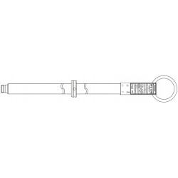
Schwarzbeck EFS 9218 Active Electric Field Probe
New
- Active Electric Field Probe with Biconical Elements
- 9 kHz - 300 MHz
- 12 µV/m - 65 V/m
- Const. antenna factor typ. 46 dB/m high symmetry
- Built in rechargeable battery
- The switchable preamplifier improves the antenna factor to 20 dB/m.
PDF Downloads
Test Equipment Description
The EFS 9218 was designed because of the growing demand for a small, light weight receiving antenna to cover the frequency range below 300 MHz. Because of the fact that dipole length is very short compared to wavelength, symmetry has to be extremely high. So optimum symmetry was the main goal of this development. Above 300 MHz small Log.-Per.-Antennas with high gain and symmetry are a good choice.
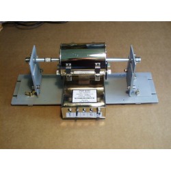
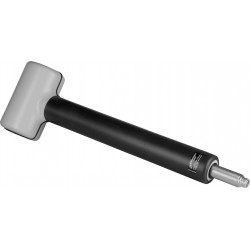
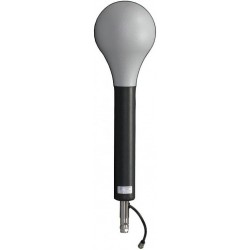
Active Electric Field Probe with Biconical Elements EFS 9218 and built-in Amplifier

Application
Typical application is frequency selective E-Field-Measurement outside and inside of buildings and rooms using test receivers or spectrum analysers. The wide frequency and dynamic range cover the limits of human protection as well as the very low limits for medical implants (heart pace-maker).
Field sources are AM and FM radio- and TV-stations. Furthermore there is a variety of military and civilian radio services, not to forget CB- and amateur radio. The antenna (conversion) factor is constant over nearly the complete frequency range giving a very natural field strength image when spectrum-analysers are in use.
In order to eliminate power supply problems and stray coupling, NiMH rechargeable batteries are built in the mounting tube. The state of the battery is monitored by a multicolour LED. After more than five hours of continuous operation, charging with the automatic charger takes about 2-4 hours. The suitable charger is the Ansmann ACS 410 or ACS 110 traveller.
The small biconical elements come with a male M4 thread, which fits into the element fixture nuts of the holder. When mounting the biconical elements care should be taken in order to avoid overtightening the threads. It is absolutely sufficient to tighten the elements with two fingers.
Built-in switchable amplifier
In contrast to common passive antennas a differential amplifier with field effect transistors is used. A common passive antenna virtually does not show internal noise or saturation, but active probes do so. Internal noise and saturation are the limiting factors for the dynamic range. Weak signals are covered by internal noise and strong signals suffer from saturation.
Internal noise and saturation depend on the length of the biconical elements and the quality of the differential amplifier, but the margin for improvement is small. When the measuring receiver is sensitive enough to show the internal noise of the probe, the system is ideally levelled and uses the whole dynamic range of the probe. When the receiver is insensitive, the sensitivity of the probe cannot be used and weak signals cannot be measured.
When the receiver is insensitive, the sensitivity of the probe cannot be used and weak signals cannot be measured. An amplifier on the output of the probe will amplify all signals below its saturation limit including the probe's inherent noise. Under these circumstances, even an insensitive receiver will measure weak signals. But this is at the expense of strong signals. A 20-dB-amplifier will reduce the dynamic range of the probe by 20 dB.
For example: The probe without amplifier could measure a field strength of 50 V/m without saturation. Using the 20-dBamplifier saturation occurs at 5 V/m. A way out of this dilemma is to make the amplifier switchable. So the dynamic range is still present with sensitive receivers and weak signals can be measured even with insensitive receivers. The conversion factor is improved from 47 dB/m without amplifier to 20 dB/m with amplifier.
There are no semiconductor switches available to cover both frequency and amplitude range. Instead low power consumption coaxial RF-relays are used.
Operation

Switching On
Set the ON/OFF switch to the ONposition. The LED should light up in green. Green: Battery OK Red: Low battery The probe will operate even with low battery, but measurement may be wrong.
Choice of Conversion Factor
Position k=47 dB/m
Measurement of high field strengths Measurement near radio stations
Position k=20 dB/m
Measurement of low field strengths with insensitive receivers and spectrum analysers
Set-up
For high precision measurement a mast should be used. Changing height and polarisation the maximum can be found while the operating person at a distance does not influence the measurement.
Hand held measurement is also possible with restricted precision. Keep the hands to the N-connector side of the mounting tube and the cable straight off the probe. E-field-measurement is more sensitive to environmental influences than Hfield. For this reason the cable should be as short as possible.
Indication equipment
Using the built-in switcheable amplifier the probe can be adapted to the sensitivity of the measuring receiver or spectrum-analyser. Broadband measurement of high field strength can also be made with other equipment.
Care has to be taken to ensure that the meter has a 50 Ω input. A BNC- or other coaxial input connector is no guaranty for that. Oscilloscopes with a BNC-inputconnector usually have an extremely high input impedance consisting of some MΩ in parallel with some pF.
Some models have a switch to put a 50-Ω−termination in parallel. The situation is more or less the same considering RF-millivolt-meters. Mismatch may be tolerated if only signal characteristics are monitored. For correct measuring a 50-Ω−termination is a necessity.
Measurement
The probe converts electrical fieldstrength into a voltage (across 50 Ω), which is indicated by a measuring receiver,spectrum analyser or RF.- millivolt meter. The field strength can be calculated using the antenna factor (conversion factor, transducer factor) of the probe. This factor is constant over the wide centre frequency range with some changes at the edges. The main antenna factor is 47 dB/m (typ.) without amplifier and 20 dB/m (typ.) with amplifier.
Example 1 for preamplifier OFF, set to display dBµV:
A measuring receiver or spectrum analyser with a 50-Ω-input and dBµVreading is used for measuring. Reading in dBµV is very common in the EMC-field and available on almost every receiver, using 0 dBµV acc. to 1 µV. The voltage level on a certain frequency (i.e. an AM transmitter at 1 MHz) is measured. The antenna factor of 47 dB (typ.) is added to the voltage level reading. The result is the electric field strength level in dBµV/m.
| Voltage level reading | |
| on the receiver | 60 dBµV |
| plus antenna factor (typ.) | 47 dB |
| Electric field strength level | 107 dBµV/m |
Example 2 for preamplifier OFF, displayed in dBm:
Receiver reading in dBm (0 dBm relates to 1 mW power into a 50 Ohm input). It takes 0.2236 V to let a power of 1 mW flow into a 50 Ohm input. 0.2236 V equals 107 dBµV. That means: 107 dBµV = 0 dBm
The power level is measured and 107 dB must be added to obtain the voltage level. Another 47 dB/m are added as antenna factor. The result is the electric field strength in dBµV/m.
| Power level reading | |
| on the receiver | -50 dBm |
| plus conversion from power to voltage | 107 dB |
| Electric field strength level | 47 dB/ |
| Is Electric field strength level | 104 dBµV/m/ |
Example 3 for preamplifier OFF display in V:
Receiver voltage reading directly in V. 47 dB/m is a logarithmic expression of the antenna factor with: 20log(223,9)=47 Thus the voltage has to be multiplied by 223,9 to get the electric field strength in V/m. Receiver reading (voltage) 0,1 V multiplied by antenna factor (typ.) 223,9 equals electric field strength 23,9 V/m
Measuring high field strengths
The linear range of the probe ends at 156 dBµV/m acc. to 60 V/m with the amplifier switched OFF. Switch amplifier OFF when measuring high field strength! Saturation begins "soft" and depends on the frequency. Higher field strength levels lead to signal distortion and intermodulation products occur in the spectrum. The same situation occurs with many weak signals. Whenever strange signals are recognised under high level conditions, increase the distance between probe and field source.
Intermodulation products then decrease faster than "real" signals. Simple receivers and spectrum analysers with no or insufficient front-end-filtering may cause intermodulation while the probe is still linear. In this case increase RF-attenuation and decrease IF-attenuation to reduce input saturation at the expense of noise.
Measuring very low field strength
When a very sensitive receiver or spectrum analyser is used, the noise of the probe is the limit for low field strength measurement.
Whenever only signals with small field strength are present in the whole frequency range of the probe, the amplifier may be switched ON.
There is potential danger of saturation, when a strong signal is present while a weak signal is measured. Making the receiver bandwidth smaller will reduce noise indication.
Under the condition that the signal to measure is a narrow-band-signal, smaller receiver bandwidth will give better signal to noise ratio.
Choosing the average detector may reduce noise even more.
There will be improvements for narrow band signals (CW) without modulation, but not for broadband signals and pulse spectrum.
The following table shows the noise of the probe. The Measurement was made with the EMI-receivers FCKL 1528 and FCVU 1534. The bandwidths are standard EMIbandwidths. Smaller bandwidths give lower noise indication.
First steps with the probe
After connecting the probe to the receiver or spectrum analyser some signals can be seen.
Spectrum Analysers usually "wake up" in a somewhat insensitive default set-up. It is therefore recommended to switch the amplifier ON.
In contrast to magnetic probes there will be a multitude of signals generated by electric and electronic equipment, but only a few broadcast transmitters. Radio AM-transmitters which can be monitored with the magnetic probe FMZB 1538 are covered by interference. This interference is produced by industrial disturbance sources which mostly emit electric field rather than magnetic field. FM-radio shows better results because some of the interference decreases with increasing frequency.
In office rooms emission is dominated by PCs, monitors and data networks. Industrial environment shows high fieldstrength on ISM-frequencies (Industrial, Scientific, Medical). Even some receivers or spectrum analysers radiate electric field strength, which can be monitored with the probe.
Battery
The probe contains 6 NiMH-cells with 1,2 V/600 mAh each resulting in a voltage of 7,2 V (nom.). The batteries are built in the antenna tube and completely shielded. Any stray coupling or other effects from outside are impossible. Power consumption is slightly higher with the amplifier switched ON. The > 5 hours of operation time is very conservative. If the colour of the battery LED changes to RED the measurement should be stopped and the antenna should be recharged. The operation time will still be available after a certain ageing of the batteries. Batteries of this kind have a very low resistance. After a short current they will heat up in seconds. Burning out of the insulating material between the cells leads to permanent inner short circuit with even more heat. The battery is protected by a fuse. But once a short circuit between cells is established, the fuse cannot prevent severe damage to the probe.
For this reason never open the probe or charge it with inappropriate charging equipment. Avoid short circuits to the charging connector. An SMA-connector was used for charging in combination with a short adapter cable to DC-jack until S/N 212. Nowadays starting from S/N 213 a DC jack is directly assembled to the EFS 9218. A slight warming of the antenna tube is normal during charging.
DC-jack for charging:
| Inner conductor | PLUS |
| Outer conductor | MINUS (GROUND) |
| Diameter of the center pin | 2,5 mm |
| Specifications | |
| Very symmetrical, active E-Fieldprobe with biconical elements | |
| Frequency range | 9 kHz - 300 MHz |
| Connector female | 50 Ω N |
| Mounting tube | 22 mm |
| Element length total | LE=140 mm |
| Element diameter | D = 49 mm |
| Element fixture | M4 |
| Antenna Factor Amplifier OFF | 47 dB/m typ. (40 kHz-250 MHz) |
| Antenna Factor Amplifier ON | 20 dB/m typ. (40 kHz-250 MHz) |
| Maximum Field strength Amplifier OFF | 65 V/m |
| Maximum Field strength Amplifier ON | 3 V/m |
| Mimimum Field strength typ. | 12 µV/m (F=30 MHz, ∆F=9 kHz, Average)* |
| Operation Time | typ. < 1 dB 100 kHz - 250 MHz |
| Inversion Symmetry | typ. < 1 dB 100 kHz - 250 MHz |
| Power Supply | 7,2 V, 600 mAh NiMH |
| Weight (incl. batteries) | >1000 g |
13 other products in the same category:
-
Schwarzbeck TK 9420 High Voltage Probe
-
Schwarzbeck CMDM 8700 Common Mode / Differential Mode Switch
-
Schwarzbeck CP 9610 Current Probe 40A DC - 1 MHz
-
Schwarzbeck CVP 9222 B High Impedance Capacitive Voltage Probe
-
Schwarzbeck CAL 9222 Calibration Jig for Capacitive Voltage Probe CVP 9222
-
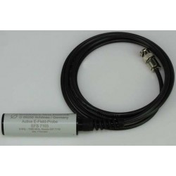
Schwarzbeck EFS 7103 Active Electric Field Probe
-
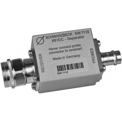
Schwarzbeck EW 7110 DC Separator
-
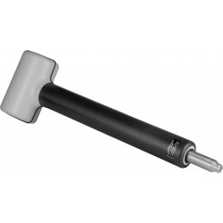
Schwarzbeck FSHPE Single Axis E-Field Antenna
-
Schwarzbeck FSHPH Single Axis H-Field Antenna
-
Schwarzbeck FSE3D Isotropic 3-axial RX Antenna
-
Schwarzbeck FMZB 1512 Active Handheld RX Loop Antenna
-
Schwarzbeck HMDA 1545 Sensitive Magnetic Field-Strength Meter with LCD Reading
-
Schwarzbeck HFS 1546 Active Magnetic Field Probe with Electrically Shielded Loop