
No products
Product successfully added to your shopping cart
There are 0 items in your cart. There is 1 item in your cart.
Schwarzbeck Mess-Elektronik
- EMC Test Equipment
- Transient Generators
- RF Power Amplifiers
- DC - 300 kHz RF Amplifiers
- 10 kHz - 250 MHz RF Amplifiers
- 10 kHz - 400 MHz RF Amplifiers
- 10 kHz - 1 GHz RF Amplifiers
- 80 MHz - 1 GHz RF Amplifiers
- 1 GHz - 2 GHz RF Amplifiers
- 700 MHz - 4.2 GHz RF Amplifiers
- 1 GHz - 6 GHz RF Amplifiers
- 2 GHz - 8 GHz RF Amplifiers
- 6 GHz - 18 GHz RF Amplifiers
- 18 GHz - 40 GHz RF Amplifiers
- Pulse Amplifiers
- RF Field Strength Probes & Meters
- RF Conducted Immunity
- EMC Receivers/EMI Analyzers
- EMC Antennas
- Coupling Decoupling Networks (CDN's)
- Line Impedance Stabilization Networks (LISN's)
- RF Test Equipment
- EMC Probes
- EMC Measurement & Equipment Software
- Power Supplies
- Electrical Safety Analyzers
- High Precision Laboratory Power Analyzers & Meters
- Anechoic Chambers
- Over-the-Air (OTA) Test Chambers
- EMI RF Shielded Tent Enclosures
- RF Shielded Rooms
- EMC Absorber
- Positioning Equipment
- EMC/EMI Test Setup
- GTEM Cells / TEM Cells
- Reverberation Chambers
- Used RF Anechoic Chambers
- EMC Chamber Filters
- EMC Chamber Shielding Gaskets
- RF Shielded Doors
- Anechoic Chamber Accessories
- Fully Anechoic (FAR) Test Chambers
- Manufacturers
- 3ctest
- AE Techron
- AH Systems
- Amplifier Research
- Boonton
- Com-Power
- Diamond Engineering
- EM Test (Ametek CTS)
- EMC Partner
- EMC Test Design
- Empower High Power RF Amplifiers
- ETS-lindgren
- Log Periodic Dipole Array Antenna
- Near Field Probe Sets
- Double Ridge Horn Antennas
- Biconical Antennas
- Quad Ridge Horn Antennas
- Electric Field Probes
- GTEM's
- Positioners & Tripods
- Loop Antennas
- Biconilog Antennas
- LISN's (Line Impedance Stabilization Network)
- Shielded Enclosures/Rooms
- Monopole Antennas
- Field Generating Antennas
- Fischer Custom Communications
- Haefely Hipotronics
- Haefely EFT/Burst Immunity Test Systems
- Haefely Surge Combination Wave Test Systems
- Haefely Surge Damped Oscillating Wave Test Systems
- Haefely Electrostatic Discharge Test Systems (ESD)
- Haefely Surge Ring Wave Test Systems
- Haefely Surge Telecom Wave Test Systems
- Haefely Magnetic Field Test Systems
- Haefely CDN's (Coupling/Decoupling Networks)
- IFI Amplifiers
- Keysight (Agilent)
- MVG - Microwave Vision Group
- PMM / Narda
- Rohde & Schwarz RF Test Equipment
- Rohde & Schwarz Broadband RF Amplifiers
- Rohde & Schwarz Spectrum Analyzers
- Rohde & Schwarz Compliant EMI Test Receivers
- Rohde & Schwarz Isotropic RF Probes
- Rohde & Schwarz RF Signal Generators
- Rohde & Schwarz RF Switches
- Rohde & Schwarz Oscilloscopes
- Rohde & Schwarz RF Power Meters
- Rohde & Schwarz RF Power Sensors
- Schloder
- Schwarzbeck Mess-Elektronik
- Schwarzbeck Antennas
- Schwarzbeck Automotive Antennas
- Schwarzbeck Broadband Horn Antennas
- Schwarzbeck Biconical Antennas
- Schwarzbeck Logarithmic Periodic Broadband Antennas
- Schwarzbeck Stacked Log-Periodic Broadband Antennas
- Schwarzbeck Biconic Log-Periodic Antennas
- Schwarzbeck Dipole Antennas
- Schwarzbeck Rod Antennas
- Schwarbeck Antenna Baluns / Holders
- Schwarzbeck LISN Line Impedance Stabilisation Networks
- Schwarbeck Decoupling & Absorbing Clamps
- Schwarzbeck Field Probes
- Schwarzbeck Helmholtz Coils
- Schwarzbeck Antenna Masts
- Schwarzbeck Coupling/Decoupling Networks
- Schwarzbeck Antennas
- Solar Electronics
- Teseq (Schaffner)
- Teseq Automotive Transient Generators
- Teseq RF Test Equipment
- Teseq EFT/Burst Generators
- Teseq RF Immunity Generators
- Teseq ESD Guns
- Teseq Surge Generators
- Teseq Harmonics & Flicker Solutions
- Teseq Dips, Interrupts & Variations Equipment
- Teseq Ring Wave Generators
- Teseq Oscillatory Waves Generators
- Teseq Absorbing Clamps / Ferrite Tube
- Teseq EMC Antennas
- Teseq Current Probes
- Teseq Coupling Networks
- Thermo Keytek
- Vicreate
- Compliance Standards
- International (IEC/EN)
- EN/IEC 61000-3-2
- EN/IEC 61000-3-3
- IEC 61000-3-11
- IEC / EN 610000-3-12
- EN/IEC 61000-4-2
- EN/IEC 61000-4-3
- EN/IEC 61000-4-4
- EN/IEC 61000-4-5
- EN/IEC 61000-4-6
- EN/IEC 61000-4-7
- EN/IEC 61000-4-8
- EN/IEC 61000-4-9
- EN/IEC 61000-4-10
- EN/IEC 61000-4-11
- EN/IEC 61000-4-12
- EN/IEC 61000-4-16
- EN/IEC 61000-4-18
- EN/IEC 61000-4-19
- EN/IEC 61000-4-20
- EN/IEC 61000-4-21
- EN/IEC 61000-4-29
- EN/IEC 61000-4-31
- IEC 61000-4-39
- EN/IEC 62132
- SEMI F47 Voltage Sag Immunity
- Product Standards
- Military & Aerospace Standards
- Automotive EMC Standards
- CISPR Standards
- Telecom Testing
- ANSI/IEEE Standards
- FCC Part 15
- FCC Part 30
- International (IEC/EN)
- Application/Test Type
- Radiated Immunity
- Bulk Current Injection Testing
- RF Emissions Testing
- Conducted Immunity
- Conducted Emissions
- Antenna Pattern Measurement
- CE Mark Testing
- Intentional Radiator Testing
- Pulsed HIRF Radar
- Over-the-Air (OTA) Testing
- 5G Test Solutions
- Automotive EMC
- SAR Measurement Equipment
- Radiated Emissions
- Battery Simulator Test Equipment
- Services
- Clearance
Viewed products
-

Schwarzbeck NFCN 9731...
DC - 150 kHz Frequency Range 1 Ohm /...
 View larger
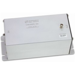
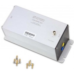
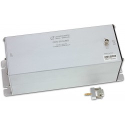
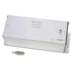
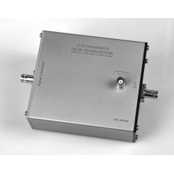
Schwarzbeck NFCN 9731 Compensation Network
New
- DC - 150 kHz Frequency Range
- 1 Ohm / 800 W Integrated Shunt
- Max continuous current: up to 32 Arms
- Capacitance range: 1.5 nF - 300 µF
- Provide a serial compensation of the inductance of the HHS 5206-16
PDF Downloads
Test Equipment Description
The primary function of the compensation network NFCN 9731 is to provide a serial compensation of the inductance of the HHS 5206-16. Thus the currents needed to produce the desired field strength can be achieved using relatively low voltages i.e. to be able to use an audio amplifier.
The compensation capacitor of the NFCN 9731 reduces the overall impedance of the series circuit with the Helmholtz coil HHS 5206-16 at the wanted operating frequency and allows currents up to 30 Arms at a generator voltage of less than 40 Vrms. An integrated shunt allows measuring the coilcurrent and serves as minimum load for the power amplifier.
The compensation network NFCN 9731 consists of a series circuit of a variable capacitor and a fuse. Its purpose is to compensate the inductance of the Helmholtz coil HHS 5206-16 at operating frequencies of 180 Hz up to 200 kHz. Up to 180 Hz no compensation is necessary and the signal is looped through.
There are 23 different capacitors and a short available. They are connected between “Power Amplifier” and “Coil (to A)” utilizing relays.
The following graph shows the maximum reachable magnetic field strength of the system (HHS 5206-16, NFPA 9730 and NFCN9731) – in relation to common standards.
Max. magnetic fieldstrength of HHS 5206-16 with NFPA 9730, NFCN 9731

Internal 1 Ohm Shunt
The integrated 1 Ohm (800W) shunt allows measuring the coil-current and serves as minimum load for the power-amplifier. The internal fans are automatically enabled if the shunt becomes hot.
The shunt can be used stand-alone without the compensation network. But the cooling fans are only working when NFCN 9731 is turned on.
The following chart shows the total impedance of the shunt versus the frequency.
| Frequency, [kHz] | Impedance “1Ω”, [Ω] |
| DC | 0.999 |
| 10 | 0.999 |
| 20 | 1.000 |
| 30 | 1.001 |
| 50 | 1.003 |
| 80 | 1.009 |
| 100 | 1.014 |
| 120 | 1.019 |
| 150 | 1.027 |
| 200 | 1.043 |
| 250 | 1.060 |
| 300 | 1.079 |
Internal low level signal attenuator
The internal switchable low level signal attenuator increases the dynamic range of the system. Therefore the attenuator is interconnected between the signal generator and the amplifier with a BNC-cable (Signal generator to the “IN” socket. The “OUT” socket to the input of the amplifier).
The attenuation of 0 dB, 20 dB or 40 dB can be switched by the relays-control-word. The signal is muted if no attenuation is set.
At low output levels the level step size of most signal generator is to big. In this case an attenuator can be used. The signal generator has to compensate the attenuation with higher output levels. Now the relationship of the step size to the output level is smaller.
Hazard warning
Attention: Life-endangering high voltages occur at the terminals of the HHS 5206-16 and the NFCN 9731 during operation. If used in an inappropriate way this could lead to a life-threatening situation for the user.
30 other products in the same category:
-
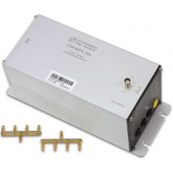
Schwarzbeck CDN M3PE 16A Coupling Decoupling Network
-
Schwarzbeck CDN M3PE 32A Coupling Decoupling Network
-
Schwarzbeck CDN M4 32A Coupling Decoupling Network
-
Schwarzbeck CDN M4 32A 1000V Coupling Decoupling Network
-
Schwarzbeck CDN M4PE 16A Coupling Decoupling Network
-
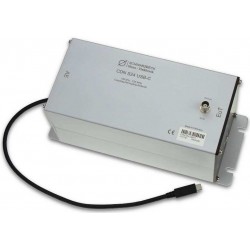
Schwarzbeck CDN USB-C Coupling Decoupling Network for IEC 61000-4-6
-
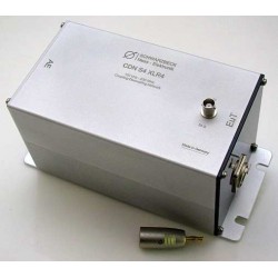
Schwarzbeck CDN S4 XLR4 Coupling Decoupling Network
-
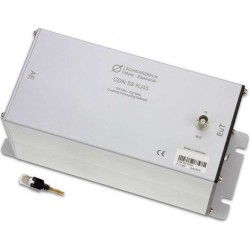
Schwarzbeck CDN S8 RJ45 Coupling Decoupling Network
-
Schwarzbeck CDN S9 SUBD Coupling Decoupling Network
-
Schwarzbeck CDN USB 3.0 Coupling Decoupling Network for IEC 61000-4-6
-
Schwarzbeck CDNE M2 Coupling Decoupling Network
-
Schwarzbeck CDNE M3 Coupling Decoupling Network
-
Schwarzbeck CNA 280 Coupling Network Type A
-
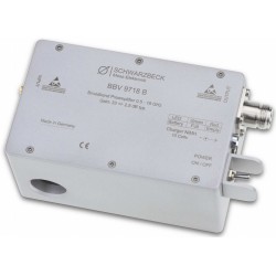
Schwarzbeck BBV 9718 B Microwave Broadband Amplifier
-
Schwarzbeck BBV 9719 Microwave Broadband Amplifier
-

Schwarzbeck BBV 9721 Microwave Broadband Preamplifier
-
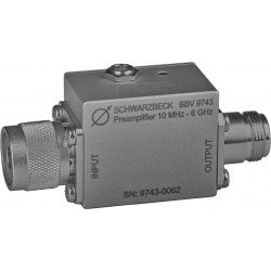
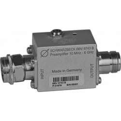
Schwarzbeck BBV 9743 Broadband Preamplifier 10 MHz - 6 GHz
-
Schwarzbeck BBV 9743 B Broadband Preamplifier
-
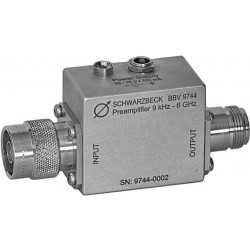
Schwarzbeck BBV 9744 Broadband Preamplifier
-
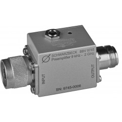
Schwarzbeck BBV 9745 Broadband Preamplifier
-
Schwarzbeck CCC 9224 Capacitive Coupling Clamp
-

Schwarzbeck NFPA 9730 Power Amplifier DC - 250 kHz
-
Schwarzbeck VDHH 9502 Van der Hoofden Test-Head
-
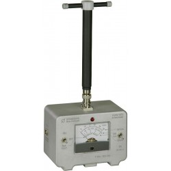
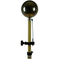
Schwarzbeck VUFM 1670 Battery Operated, Direct Indication E-Field-Meter
-
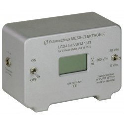
Schwarzbeck VUFM 1671 LCD-Display Unit For VUFM 1670
-
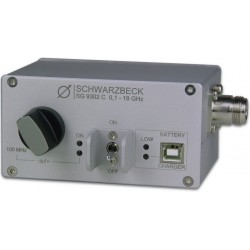
Schwarzbeck SG 9302 C Comb - Generator with 100 MHz Spectrum Lines
-

Schwarzbeck IGUU 2918 Calibration-Pulse Generator
-
Schwarzbeck SG 9301 Spectrum Generator
-

Schwarzbeck SG 9302 B Comb - Generator with 100 MHz Spectrum Lines
-
Schwarzbeck IGUU 2916 Universal Calibration Pulse Generator