
No products
Product successfully added to your shopping cart
There are 0 items in your cart. There is 1 item in your cart.
Schwarzbeck Mess-Elektronik
- EMC Test Equipment
- Transient Generators
- RF Power Amplifiers
- DC - 300 kHz RF Amplifiers
- 10 kHz - 250 MHz RF Amplifiers
- 10 kHz - 400 MHz RF Amplifiers
- 10 kHz - 1 GHz RF Amplifiers
- 80 MHz - 1 GHz RF Amplifiers
- 1 GHz - 2 GHz RF Amplifiers
- 700 MHz - 4.2 GHz RF Amplifiers
- 1 GHz - 6 GHz RF Amplifiers
- 2 GHz - 8 GHz RF Amplifiers
- 6 GHz - 18 GHz RF Amplifiers
- 18 GHz - 40 GHz RF Amplifiers
- Pulse Amplifiers
- RF Field Strength Probes & Meters
- RF Conducted Immunity
- EMC Receivers/EMI Analyzers
- EMC Antennas
- Coupling Decoupling Networks (CDN's)
- Line Impedance Stabilization Networks (LISN's)
- RF Test Equipment
- EMC Probes
- EMC Measurement & Equipment Software
- Power Supplies
- Electrical Safety Analyzers
- High Precision Laboratory Power Analyzers & Meters
- Anechoic Chambers
- Over-the-Air (OTA) Test Chambers
- EMI RF Shielded Tent Enclosures
- RF Shielded Rooms
- EMC Absorber
- Positioning Equipment
- EMC/EMI Test Setup
- GTEM Cells / TEM Cells
- Reverberation Chambers
- Used RF Anechoic Chambers
- EMC Chamber Filters
- EMC Chamber Shielding Gaskets
- RF Shielded Doors
- Anechoic Chamber Accessories
- Fully Anechoic (FAR) Test Chambers
- Manufacturers
- 3ctest
- AE Techron
- AH Systems
- Amplifier Research
- Boonton
- Com-Power
- Diamond Engineering
- EM Test (Ametek CTS)
- EMC Partner
- EMC Test Design
- Empower High Power RF Amplifiers
- ETS-lindgren
- Log Periodic Dipole Array Antenna
- Near Field Probe Sets
- Double Ridge Horn Antennas
- Biconical Antennas
- Quad Ridge Horn Antennas
- Electric Field Probes
- GTEM's
- Positioners & Tripods
- Loop Antennas
- Biconilog Antennas
- LISN's (Line Impedance Stabilization Network)
- Shielded Enclosures/Rooms
- Monopole Antennas
- Field Generating Antennas
- Fischer Custom Communications
- Haefely Hipotronics
- Haefely EFT/Burst Immunity Test Systems
- Haefely Surge Combination Wave Test Systems
- Haefely Surge Damped Oscillating Wave Test Systems
- Haefely Electrostatic Discharge Test Systems (ESD)
- Haefely Surge Ring Wave Test Systems
- Haefely Surge Telecom Wave Test Systems
- Haefely Magnetic Field Test Systems
- Haefely CDN's (Coupling/Decoupling Networks)
- IFI Amplifiers
- Keysight (Agilent)
- MVG - Microwave Vision Group
- PMM / Narda
- Rohde & Schwarz RF Test Equipment
- Rohde & Schwarz Broadband RF Amplifiers
- Rohde & Schwarz Spectrum Analyzers
- Rohde & Schwarz Compliant EMI Test Receivers
- Rohde & Schwarz Isotropic RF Probes
- Rohde & Schwarz RF Signal Generators
- Rohde & Schwarz RF Switches
- Rohde & Schwarz Oscilloscopes
- Rohde & Schwarz RF Power Meters
- Rohde & Schwarz RF Power Sensors
- Schloder
- Schwarzbeck Mess-Elektronik
- Schwarzbeck Antennas
- Schwarzbeck Automotive Antennas
- Schwarzbeck Broadband Horn Antennas
- Schwarzbeck Biconical Antennas
- Schwarzbeck Logarithmic Periodic Broadband Antennas
- Schwarzbeck Stacked Log-Periodic Broadband Antennas
- Schwarzbeck Biconic Log-Periodic Antennas
- Schwarzbeck Dipole Antennas
- Schwarzbeck Rod Antennas
- Schwarbeck Antenna Baluns / Holders
- Schwarzbeck LISN Line Impedance Stabilisation Networks
- Schwarbeck Decoupling & Absorbing Clamps
- Schwarzbeck Field Probes
- Schwarzbeck Helmholtz Coils
- Schwarzbeck Antenna Masts
- Schwarzbeck Coupling/Decoupling Networks
- Schwarzbeck Antennas
- Solar Electronics
- Teseq (Schaffner)
- Teseq Automotive Transient Generators
- Teseq RF Test Equipment
- Teseq EFT/Burst Generators
- Teseq RF Immunity Generators
- Teseq ESD Guns
- Teseq Surge Generators
- Teseq Harmonics & Flicker Solutions
- Teseq Dips, Interrupts & Variations Equipment
- Teseq Ring Wave Generators
- Teseq Oscillatory Waves Generators
- Teseq Absorbing Clamps / Ferrite Tube
- Teseq EMC Antennas
- Teseq Current Probes
- Teseq Coupling Networks
- Thermo Keytek
- Vicreate
- Compliance Standards
- International (IEC/EN)
- EN/IEC 61000-3-2
- EN/IEC 61000-3-3
- IEC 61000-3-11
- IEC / EN 610000-3-12
- EN/IEC 61000-4-2
- EN/IEC 61000-4-3
- EN/IEC 61000-4-4
- EN/IEC 61000-4-5
- EN/IEC 61000-4-6
- EN/IEC 61000-4-7
- EN/IEC 61000-4-8
- EN/IEC 61000-4-9
- EN/IEC 61000-4-10
- EN/IEC 61000-4-11
- EN/IEC 61000-4-12
- EN/IEC 61000-4-16
- EN/IEC 61000-4-18
- EN/IEC 61000-4-19
- EN/IEC 61000-4-20
- EN/IEC 61000-4-21
- EN/IEC 61000-4-29
- EN/IEC 61000-4-31
- IEC 61000-4-39
- EN/IEC 62132
- SEMI F47 Voltage Sag Immunity
- Product Standards
- Military & Aerospace Standards
- Automotive EMC Standards
- CISPR Standards
- Telecom Testing
- ANSI/IEEE Standards
- FCC Part 15
- FCC Part 30
- International (IEC/EN)
- Application/Test Type
- Radiated Immunity
- Bulk Current Injection Testing
- RF Emissions Testing
- Conducted Immunity
- Conducted Emissions
- Antenna Pattern Measurement
- CE Mark Testing
- Intentional Radiator Testing
- Pulsed HIRF Radar
- Over-the-Air (OTA) Testing
- 5G Test Solutions
- Automotive EMC
- SAR Measurement Equipment
- Radiated Emissions
- Battery Simulator Test Equipment
- Services
- Clearance
Viewed products
-

Schwarzbeck VDHH 9502...
Van der Hoofden test head With...
 View larger
Schwarzbeck VDHH 9502 Van der Hoofden Test-Head
New
- Van der Hoofden test head
- With protection network and;
- Individual calibration of the network acc. IEC 62493:2015 or VDE 0848-493
- Allows to determine the exposure of humans to radiation caused by luminaries
PDF Downloads
Test Equipment Description
The "Van der Hoofden" Test head VDHH 9502 allows to determine the exposure of humans to radiation caused by luminaries. The measurement is based on DIN IEC 62493:2015 and VDE 0848-493. Through different ways of coupling between luminaries and humans a level of exposure of a person to electromagnetic fields can be derived. One part of the exposure is based on capacitive coupling between lighting equipment and person. This induces current densities. These current densities must be measured and evaluated using an EMI receiver and a van der Hoofden test head.
Measurement Procedure:
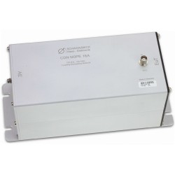
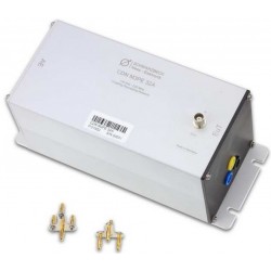
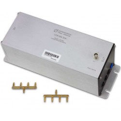
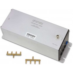
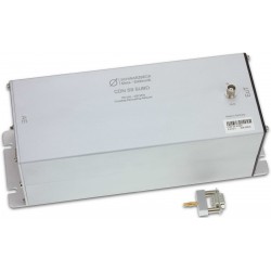
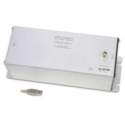
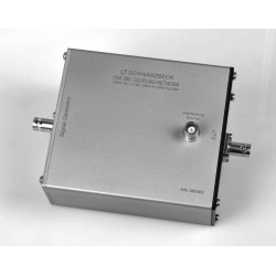
The van der Hoofden test head consists of 3 elements: An electrically conductive sphere with a diameter of 210 mm, a connection line of 300 mm length, and a protection network for the EMI receiver.
The test head is equipped with a 3/8’’ female thread. It can be mounted on an insulated mast system with height adjustment. The protection network is housed in the mast fixture clamp. It has to be connected with the test head via the 300 mm cable which is included in the delivery. The cable is equipped with 4 mm banana plugs. The clamp with the protection network must be fixed to the mast below the head.
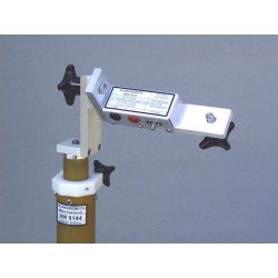
A perfectly suited mast system is the AM 9144 with option “very short”. This allows a height set range of 0.8 - 1.4 m. The lowest required height acc. IEC62493 is 0.8 m. AM 9144 allows to continuously adjust the height up to 1.4 m in telescopic manner. Adding extender pieces of fixed lengths 0.6 and 1.2 m allows to continuously adjust the range from 0.8 to 3.2 m.
The EMI receiver measures a voltage across 50 Ω. It must be connected to the BNC connector of the mast clamp. To determine the compliance of a luminaire to the standard the measured voltages must be converted into induced current densities. The measured densities must be expressed in relation to the allowed densities and they must be summed up. The result is a factor called F. A DuT is compliant if F does not exceed 0.85. These calculations are readily integrated into the Messbase Software. The measurement can be performed using the following receiver types: FCKL 1528, FMLK 1518, FCLE 1535. If a different type of receiver is used or if the Messbase software is not available the program “Van der HoofdenTest” can be used to calculate F from the measured voltages.

Fig. 1 transmission of the protective circuit
Testing according to IEC 62493 with the Schwarzbeck Messbase software
Acc. to IEC 62493 the following receiver settings should be used
- Band A, 20 kHz – 150 kHz, Peak Detector, 220 Hz Step size, direct input, Low Distortion, measuring time 100 ms, band width 200 Hz.
- Band B, 150 kHz – 10 MHz, Peak Detector, 10 kHz Step size, direct input, Low Distortion, measuring time 20 ms, bandwidth 9 kHz.
No correction may be used. No antenna factor files may be loaded! The measurements can be performed separately for band A and band B or automatically sequenced using the makro „Makro komplex“. The setup files for this makro can be found in the Messbase application folder (VanHoofdenFCKL, VanHoofdenFMLK, VanHoofdenFCLE).
The setups contain 2 templates. Attention, possible source of errors: The measurements have to be performed separately for band A and B because different measurement times must be used for each band.
After the measurements are completed and saved the factor F can be calculated. To perform the calculation the measurements must be loaded on position 1 and 2 into the Messbase software. It does not matter if the band A or band B is loaded to position 1 or 2. After that the button ![]() must be clicked on the task bar. During the calculation the band A and band B measurements are combined and the factor F is calculated and entered into the last comment line. Finally the measurement result should be saved.
must be clicked on the task bar. During the calculation the band A and band B measurements are combined and the factor F is calculated and entered into the last comment line. Finally the measurement result should be saved.
Calculation of the F-Factor with the standalone software
If the Messbase software is not available or a different meter is used the downloadable software „Van der Hoofden Test“ can be used. It allows to calculate F from the measured voltages. The data must have the following format:
Frequency1,Level1
...
...
FrequencyN,LevelN
Frequency must be given in kHz and Level in dBµV. With a click on the button “File” the suitable file can be selected, with a click on “calculate” the factor F is computed.
Especially for the Rohde & Schwarz measurement receiver the “Van_der_Hoofden_Test_RSFormat.exe” software should be used. An example file is included. The software works with Windows XP and Windows 8, Windows Vista and Windows 7 need the additionally installation of “vcredist_x86.exe” respectively “vcredist_x64.exe” software. This software can be downloaded from the Microsoft-Support webpage.

Fig. 2 Van der Hoofden Test Calculator Software
30 other products in the same category:
-
Schwarzbeck CDN M3PE 16A Coupling Decoupling Network
-
Schwarzbeck CDN M3PE 32A Coupling Decoupling Network
-
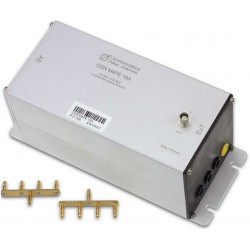
Schwarzbeck CDN M4 32A Coupling Decoupling Network
-
Schwarzbeck CDN M4 32A 1000V Coupling Decoupling Network
-
Schwarzbeck CDN M4PE 16A Coupling Decoupling Network
-
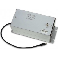
Schwarzbeck CDN USB-C Coupling Decoupling Network for IEC 61000-4-6
-
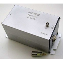
Schwarzbeck CDN S4 XLR4 Coupling Decoupling Network
-
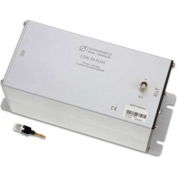
Schwarzbeck CDN S8 RJ45 Coupling Decoupling Network
-
Schwarzbeck CDN S9 SUBD Coupling Decoupling Network
-
Schwarzbeck CDN USB 3.0 Coupling Decoupling Network for IEC 61000-4-6
-
Schwarzbeck CDNE M2 Coupling Decoupling Network
-
Schwarzbeck CDNE M3 Coupling Decoupling Network
-
Schwarzbeck CNA 280 Coupling Network Type A
-
Schwarzbeck BBV 9718 B Microwave Broadband Amplifier
-
Schwarzbeck BBV 9719 Microwave Broadband Amplifier
-

Schwarzbeck BBV 9721 Microwave Broadband Preamplifier
-
Schwarzbeck BBV 9743 Broadband Preamplifier 10 MHz - 6 GHz
-
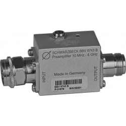
Schwarzbeck BBV 9743 B Broadband Preamplifier
-
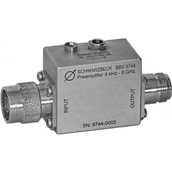
Schwarzbeck BBV 9744 Broadband Preamplifier
-
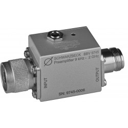
Schwarzbeck BBV 9745 Broadband Preamplifier
-
Schwarzbeck CCC 9224 Capacitive Coupling Clamp
-
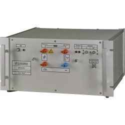
Schwarzbeck NFCN 9731 Compensation Network
-

Schwarzbeck NFPA 9730 Power Amplifier DC - 250 kHz
-
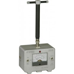
Schwarzbeck VUFM 1670 Battery Operated, Direct Indication E-Field-Meter
-
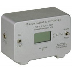
Schwarzbeck VUFM 1671 LCD-Display Unit For VUFM 1670
-
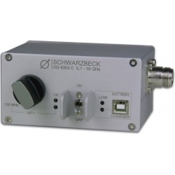
Schwarzbeck SG 9302 C Comb - Generator with 100 MHz Spectrum Lines
-

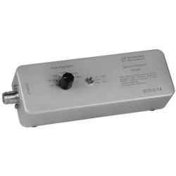
Schwarzbeck IGUU 2918 Calibration-Pulse Generator
-
Schwarzbeck SG 9301 Spectrum Generator
-

Schwarzbeck SG 9302 B Comb - Generator with 100 MHz Spectrum Lines
-
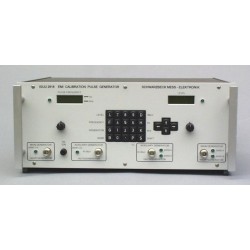
Schwarzbeck IGUU 2916 Universal Calibration Pulse Generator