
No products
Product successfully added to your shopping cart
There are 0 items in your cart. There is 1 item in your cart.
RF Power Line CDN's
- EMC Test Equipment
- Transient Generators
- RF Power Amplifiers
- DC - 300 kHz RF Amplifiers
- 10 kHz - 250 MHz RF Amplifiers
- 10 kHz - 400 MHz RF Amplifiers
- 10 kHz - 1 GHz RF Amplifiers
- 80 MHz - 1 GHz RF Amplifiers
- 1 GHz - 2 GHz RF Amplifiers
- 700 MHz - 4.2 GHz RF Amplifiers
- 1 GHz - 6 GHz RF Amplifiers
- 2 GHz - 8 GHz RF Amplifiers
- 6 GHz - 18 GHz RF Amplifiers
- 18 GHz - 40 GHz RF Amplifiers
- Pulse Amplifiers
- RF Field Strength Probes & Meters
- RF Conducted Immunity
- EMC Receivers/EMI Analyzers
- EMC Antennas
- Coupling Decoupling Networks (CDN's)
- Line Impedance Stabilization Networks (LISN's)
- RF Test Equipment
- EMC Probes
- EMC Measurement & Equipment Software
- Power Supplies
- Electrical Safety Analyzers
- High Precision Laboratory Power Analyzers & Meters
- Anechoic Chambers
- Over-the-Air (OTA) Test Chambers
- EMI RF Shielded Tent Enclosures
- RF Shielded Rooms
- EMC Absorber
- Positioning Equipment
- EMC/EMI Test Setup
- GTEM Cells / TEM Cells
- Reverberation Chambers
- Used RF Anechoic Chambers
- EMC Chamber Filters
- EMC Chamber Shielding Gaskets
- RF Shielded Doors
- Anechoic Chamber Accessories
- Fully Anechoic (FAR) Test Chambers
- Manufacturers
- 3ctest
- AE Techron
- AH Systems
- Amplifier Research
- Boonton
- Com-Power
- Diamond Engineering
- EM Test (Ametek CTS)
- EMC Partner
- EMC Test Design
- Empower High Power RF Amplifiers
- ETS-lindgren
- Log Periodic Dipole Array Antenna
- Near Field Probe Sets
- Double Ridge Horn Antennas
- Biconical Antennas
- Quad Ridge Horn Antennas
- Electric Field Probes
- GTEM's
- Positioners & Tripods
- Loop Antennas
- Biconilog Antennas
- LISN's (Line Impedance Stabilization Network)
- Shielded Enclosures/Rooms
- Monopole Antennas
- Field Generating Antennas
- Fischer Custom Communications
- Haefely Hipotronics
- Haefely EFT/Burst Immunity Test Systems
- Haefely Surge Combination Wave Test Systems
- Haefely Surge Damped Oscillating Wave Test Systems
- Haefely Electrostatic Discharge Test Systems (ESD)
- Haefely Surge Ring Wave Test Systems
- Haefely Surge Telecom Wave Test Systems
- Haefely Magnetic Field Test Systems
- Haefely CDN's (Coupling/Decoupling Networks)
- IFI Amplifiers
- Keysight (Agilent)
- MVG - Microwave Vision Group
- PMM / Narda
- Rohde & Schwarz RF Test Equipment
- Rohde & Schwarz Broadband RF Amplifiers
- Rohde & Schwarz Spectrum Analyzers
- Rohde & Schwarz Compliant EMI Test Receivers
- Rohde & Schwarz Isotropic RF Probes
- Rohde & Schwarz RF Signal Generators
- Rohde & Schwarz RF Switches
- Rohde & Schwarz Oscilloscopes
- Rohde & Schwarz RF Power Meters
- Rohde & Schwarz RF Power Sensors
- Schloder
- Schwarzbeck Mess-Elektronik
- Schwarzbeck Antennas
- Schwarzbeck Automotive Antennas
- Schwarzbeck Broadband Horn Antennas
- Schwarzbeck Biconical Antennas
- Schwarzbeck Logarithmic Periodic Broadband Antennas
- Schwarzbeck Stacked Log-Periodic Broadband Antennas
- Schwarzbeck Biconic Log-Periodic Antennas
- Schwarzbeck Dipole Antennas
- Schwarzbeck Rod Antennas
- Schwarbeck Antenna Baluns / Holders
- Schwarzbeck LISN Line Impedance Stabilisation Networks
- Schwarbeck Decoupling & Absorbing Clamps
- Schwarzbeck Field Probes
- Schwarzbeck Helmholtz Coils
- Schwarzbeck Antenna Masts
- Schwarzbeck Coupling/Decoupling Networks
- Schwarzbeck Antennas
- Solar Electronics
- Teseq (Schaffner)
- Teseq Automotive Transient Generators
- Teseq RF Test Equipment
- Teseq EFT/Burst Generators
- Teseq RF Immunity Generators
- Teseq ESD Guns
- Teseq Surge Generators
- Teseq Harmonics & Flicker Solutions
- Teseq Dips, Interrupts & Variations Equipment
- Teseq Ring Wave Generators
- Teseq Oscillatory Waves Generators
- Teseq Absorbing Clamps / Ferrite Tube
- Teseq EMC Antennas
- Teseq Current Probes
- Teseq Coupling Networks
- Thermo Keytek
- Vicreate
- Compliance Standards
- International (IEC/EN)
- EN/IEC 61000-3-2
- EN/IEC 61000-3-3
- IEC 61000-3-11
- IEC / EN 610000-3-12
- EN/IEC 61000-4-2
- EN/IEC 61000-4-3
- EN/IEC 61000-4-4
- EN/IEC 61000-4-5
- EN/IEC 61000-4-6
- EN/IEC 61000-4-7
- EN/IEC 61000-4-8
- EN/IEC 61000-4-9
- EN/IEC 61000-4-10
- EN/IEC 61000-4-11
- EN/IEC 61000-4-12
- EN/IEC 61000-4-16
- EN/IEC 61000-4-18
- EN/IEC 61000-4-19
- EN/IEC 61000-4-20
- EN/IEC 61000-4-21
- EN/IEC 61000-4-29
- EN/IEC 61000-4-31
- IEC 61000-4-39
- EN/IEC 62132
- SEMI F47 Voltage Sag Immunity
- Product Standards
- Military & Aerospace Standards
- Automotive EMC Standards
- CISPR Standards
- Telecom Testing
- ANSI/IEEE Standards
- FCC Part 15
- FCC Part 30
- International (IEC/EN)
- Application/Test Type
- Radiated Immunity
- Bulk Current Injection Testing
- RF Emissions Testing
- Conducted Immunity
- Conducted Emissions
- Antenna Pattern Measurement
- CE Mark Testing
- Intentional Radiator Testing
- Pulsed HIRF Radar
- Over-the-Air (OTA) Testing
- 5G Test Solutions
- Automotive EMC
- SAR Measurement Equipment
- Radiated Emissions
- Battery Simulator Test Equipment
- Services
- Clearance
Viewed products
-

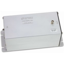
Schwarzbeck CDN M3PE...
150 kHz - 230 MHz 4 mm Safety Banana...
-

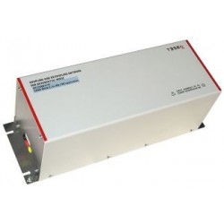
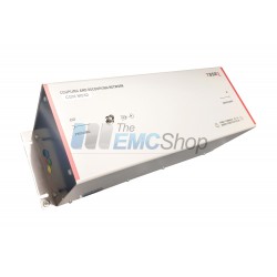
Teseq CDN 3043 Three...
Compliant with IEC 61000-4-4 & 5...
 View larger

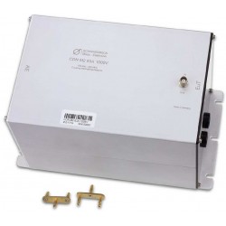
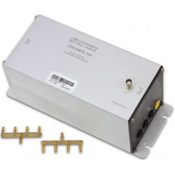
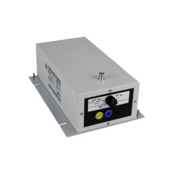
Schwarzbeck CDN M3PE 32A Coupling Decoupling Network
New
- 150 kHz - 230 MHz
- 4 mm Safety Banana Sockets
- 32 A Max. Current Rating
- 250 VAC 400 VDC Input Voltage EUT
PDF Downloads
Test Equipment Description
The Schwarzbeck CDN M3PE 32A is part of the coupling decoupling network series for conducted common mode immunity testing according to IEC 61000-4-6. The CDN M3 32A is compliant to IEC 61000-4-6 Annex D.2 and is suitable for immunity testing on unscreened a.c. and d.c. power supply lines (mains lines).
The CDN M3PE 32A is intended to inject common mode disturbance signals to power supply or mains lines (unscreened) in the frequency range from 150 kHz to 230 MHz. The circuitry is shown in Fig. 5.
All CDNs comply to the requirements of IEC 61000-4-6. Each CDN comes with individually measured data and a calibration certificate for the common mode impedance and the voltage division factor. Further typical data can be found in fig. 3 and fig. 4
Corresponding terminals are always located in opposite position and can be recognized by the terminal color. They can be used for any phase, except for PE! The PE-terminal with its yellow-green color is connected to the metal housing at the AE-side.
The connection to ground can be accomplished using the ground plane of the CDN. Additionally there is a M4 thread located at the AE side to ground as well as a 4 mm socket to connect the device to ground. The CDN is equipped with 4 mounting notches of 6 mm width at the baseplate.
To improve the operational safety the mains voltage-carrying connections are carried out as security sockets. We recommend to use special 4 mm security plugs if you plan to design your own adapters. Those connectors can be purchased optionally.
 |  |
| Fig. 1: typ. EuT common mode impedance | Fig. 2: typ. phase EuT-Port, (common mode), informative |
 |  |
| Fig. 3: typ. voltage division factor RF-port to EuT-port | Fig. 4: typ. Isolation between AE and RF-Port, informative |

| Specifications | |
| Frequency range | 150 kHz … 230 MHz |
| Common mode impedance | 150 kHz – 24 MHz: 150 Ω ±20 Ω 24 MHz – 80 MHz: 150 Ω +60 Ω/-45 Ω 80 MHz – 230 MHz: 150 Ω ±60 Ω |
| Max. RF-test voltage (emf) | 30 V |
| RF-input-power | 6 W (continuous) |
| RF-input-connector | 50 Ω BNC (female) |
| Voltage division factor RF-input – EuT-por | 9.5 dB 150 kHz – 80 MHz: ± 1dB 80 MHz – 300 MHz: +3 dB / - 2 dB |
| Input voltage EuT (AE) | 250 V AC 400 V DC |
| Housing material | 32 A (30 min. alternate) |
| Current max | Aluminium |
| Housing dimensions | 216 x 105 x 108 mm |
| Weight | ca. 1800 g |
| EuT, AE connectors | 4 mm safaty banana jacks |
| Included accessories | CA 3/4 |
| 3 Pin shorting bar | (2 units included by default) |
| Optional accessories 30 mm distance adapter 50 Ω to 150 Ω adapter | SR 30/4 SR 100-6W |
Associated EMC Test Equipment

30 other products in the same category:
-
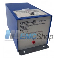
Com-Power CDN-M125E Coupling Decoupling Network
-

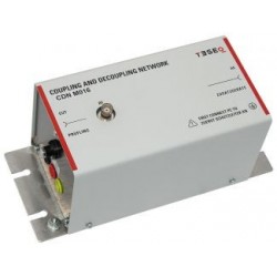
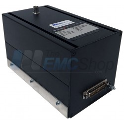
Rent Teseq CDN M016 Switchable 16 Amp Coupling/Decoupling Network
-

EM Test (Lüthi) CDN M5 5-Line Coupling/Decoupling Network (L1+L2+L3+N+PE)
-
EM Test (Lüthi) CDN M4 4-Line Coupling/Decoupling Network 3 Phase + Earth/Ground
-
EM Test (Lüthi) CDN M3-32 240 Volt Switching Coupling/Decoupling Network
-
EM Test (Lüthi) M1 CDN for Earth Conductor 250V AC / 1,000V DC
-
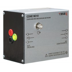
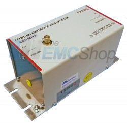
Teseq CDNE M310 Coupling/Decoupling Network for Emission Measurement, 10 A, 30 to 300 MHz
-
Teseq CDN M216 1kV CDN for CISPR 16-1-2, CISPR 16-2-1 and CISPR 15
-

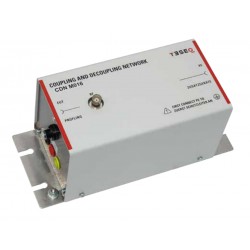
Teseq CDN M1-10 Coupling Network 10 KHz to 80 MHz for PE Lines
-
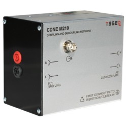
Teseq CDN M210B Coupling Network with CEE 7/17 EUT Port & IEC 60320 C14 AE Port
-
Teseq CDN M316 Coupling/Decoupling Network (CDN) CDN M3 Type
-

Teseq CDN M416 4-Line Coupling/Decoupling Network
-

Teseq CDN M432 32 Amp Coupling/Dcoupling Network
-

Teseq CDN M5 5-Line Coupling Network for AC Power Lines, 16-32 Amps
-
Dressler S-25 Coupling/Decoupling Networks (CDN) 150 kHz-230 MHz
-
Teseq M116S Series CDN for Unscreened AC or DC Power Supply Applications
-
Teseq M2 Series Coupling/Decoupling Network for Unscreened AC or DC Power Supply Applications
-
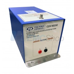
Com-Power CDN-M225E Coupling Decoupling Network for Unscreened Power Supply Lines
-
Fischer Custom Communications FCC-801-M2-16A, 2 Line M Series CDN for IEC 61000-4-6 Conducted Immunity
-
Fischer Custom Communications FCC-801-M3-16A, 3 Line M Series CDN, 150 kHz – 230MHz, 16 Amp
-
Schloder CDN M4-32_10 10 kHz – 230 MHz Coupling Network
-
Schwarzbeck CDN M1 16A Coupling Decoupling Network
-
Schwarzbeck CDN M2 16A 1000V Coupling Decoupling Network
-
Schloder M Type CDN's for Disturbance Signals to Unscreened Supply Lines (mains) AC + DC up to 1000V, 100A
-
Schwarzbeck CDN M2 32A 1000V Coupling Decoupling Network
-
Schwarzbeck CDN M2 63A 1000V Coupling Decoupling Network
-
Schwarzbeck CDN M3PE 16A Coupling Decoupling Network
-
Schwarzbeck CDN M4PE 16A Coupling Decoupling Network
-
Teseq CDN M532 5-Line/32 Amp RF Coupling/Decoupling Network
-
CDN-M3-32A-HV AC + DC 1000V, 100A Coupling/Decoupling Network