No products
Product successfully added to your shopping cart
There are 0 items in your cart. There is 1 item in your cart.
Schwarzbeck Mess-Elektronik
- EMC Test Equipment
- Transient Generators
- RF Power Amplifiers
- DC - 300 kHz RF Amplifiers
- 10 kHz - 250 MHz RF Amplifiers
- 10 kHz - 400 MHz RF Amplifiers
- 10 kHz - 1 GHz RF Amplifiers
- 80 MHz - 1 GHz RF Amplifiers
- 1 GHz - 2 GHz RF Amplifiers
- 700 MHz - 4.2 GHz RF Amplifiers
- 1 GHz - 6 GHz RF Amplifiers
- 2 GHz - 8 GHz RF Amplifiers
- 6 GHz - 18 GHz RF Amplifiers
- 18 GHz - 40 GHz RF Amplifiers
- Pulse Amplifiers
- RF Field Strength Probes & Meters
- RF Conducted Immunity
- EMC Receivers/EMI Analyzers
- EMC Antennas
- Coupling Decoupling Networks (CDN's)
- Line Impedance Stabilization Networks (LISN's)
- RF Test Equipment
- EMC Probes
- EMC Measurement & Equipment Software
- Power Supplies
- Electrical Safety Analyzers
- High Precision Laboratory Power Analyzers & Meters
- Anechoic Chambers
- Over-the-Air (OTA) Test Chambers
- EMI RF Shielded Tent Enclosures
- RF Shielded Rooms
- EMC Absorber
- Positioning Equipment
- EMC/EMI Test Setup
- GTEM Cells / TEM Cells
- Reverberation Chambers
- Used RF Anechoic Chambers
- EMC Chamber Filters
- EMC Chamber Shielding Gaskets
- RF Shielded Doors
- Anechoic Chamber Accessories
- Fully Anechoic (FAR) Test Chambers
- Manufacturers
- 3ctest
- AE Techron
- AH Systems
- Amplifier Research
- Boonton
- Com-Power
- Diamond Engineering
- EM Test (Ametek CTS)
- EMC Partner
- EMC Test Design
- Empower High Power RF Amplifiers
- ETS-lindgren
- Log Periodic Dipole Array Antenna
- Near Field Probe Sets
- Double Ridge Horn Antennas
- Biconical Antennas
- Quad Ridge Horn Antennas
- Electric Field Probes
- GTEM's
- Positioners & Tripods
- Loop Antennas
- Biconilog Antennas
- LISN's (Line Impedance Stabilization Network)
- Shielded Enclosures/Rooms
- Monopole Antennas
- Field Generating Antennas
- Fischer Custom Communications
- Haefely Hipotronics
- Haefely EFT/Burst Immunity Test Systems
- Haefely Surge Combination Wave Test Systems
- Haefely Surge Damped Oscillating Wave Test Systems
- Haefely Electrostatic Discharge Test Systems (ESD)
- Haefely Surge Ring Wave Test Systems
- Haefely Surge Telecom Wave Test Systems
- Haefely Magnetic Field Test Systems
- Haefely CDN's (Coupling/Decoupling Networks)
- IFI Amplifiers
- Keysight (Agilent)
- MVG - Microwave Vision Group
- PMM / Narda
- Rohde & Schwarz RF Test Equipment
- Rohde & Schwarz Broadband RF Amplifiers
- Rohde & Schwarz Spectrum Analyzers
- Rohde & Schwarz Compliant EMI Test Receivers
- Rohde & Schwarz Isotropic RF Probes
- Rohde & Schwarz RF Signal Generators
- Rohde & Schwarz RF Switches
- Rohde & Schwarz Oscilloscopes
- Rohde & Schwarz RF Power Meters
- Rohde & Schwarz RF Power Sensors
- Schloder
- Schwarzbeck Mess-Elektronik
- Schwarzbeck Antennas
- Schwarzbeck Automotive Antennas
- Schwarzbeck Broadband Horn Antennas
- Schwarzbeck Biconical Antennas
- Schwarzbeck Logarithmic Periodic Broadband Antennas
- Schwarzbeck Stacked Log-Periodic Broadband Antennas
- Schwarzbeck Biconic Log-Periodic Antennas
- Schwarzbeck Dipole Antennas
- Schwarzbeck Rod Antennas
- Schwarbeck Antenna Baluns / Holders
- Schwarzbeck LISN Line Impedance Stabilisation Networks
- Schwarbeck Decoupling & Absorbing Clamps
- Schwarzbeck Field Probes
- Schwarzbeck Helmholtz Coils
- Schwarzbeck Antenna Masts
- Schwarzbeck Coupling/Decoupling Networks
- Schwarzbeck Antennas
- Solar Electronics
- Teseq (Schaffner)
- Teseq Automotive Transient Generators
- Teseq RF Test Equipment
- Teseq EFT/Burst Generators
- Teseq RF Immunity Generators
- Teseq ESD Guns
- Teseq Surge Generators
- Teseq Harmonics & Flicker Solutions
- Teseq Dips, Interrupts & Variations Equipment
- Teseq Ring Wave Generators
- Teseq Oscillatory Waves Generators
- Teseq Absorbing Clamps / Ferrite Tube
- Teseq EMC Antennas
- Teseq Current Probes
- Teseq Coupling Networks
- Thermo Keytek
- Vicreate
- Compliance Standards
- International (IEC/EN)
- EN/IEC 61000-3-2
- EN/IEC 61000-3-3
- IEC 61000-3-11
- IEC / EN 610000-3-12
- EN/IEC 61000-4-2
- EN/IEC 61000-4-3
- EN/IEC 61000-4-4
- EN/IEC 61000-4-5
- EN/IEC 61000-4-6
- EN/IEC 61000-4-7
- EN/IEC 61000-4-8
- EN/IEC 61000-4-9
- EN/IEC 61000-4-10
- EN/IEC 61000-4-11
- EN/IEC 61000-4-12
- EN/IEC 61000-4-16
- EN/IEC 61000-4-18
- EN/IEC 61000-4-19
- EN/IEC 61000-4-20
- EN/IEC 61000-4-21
- EN/IEC 61000-4-29
- EN/IEC 61000-4-31
- IEC 61000-4-39
- EN/IEC 62132
- SEMI F47 Voltage Sag Immunity
- Product Standards
- Military & Aerospace Standards
- Automotive EMC Standards
- CISPR Standards
- Telecom Testing
- ANSI/IEEE Standards
- FCC Part 15
- FCC Part 30
- International (IEC/EN)
- Application/Test Type
- Radiated Immunity
- Bulk Current Injection Testing
- RF Emissions Testing
- Conducted Immunity
- Conducted Emissions
- Antenna Pattern Measurement
- CE Mark Testing
- Intentional Radiator Testing
- Pulsed HIRF Radar
- Over-the-Air (OTA) Testing
- 5G Test Solutions
- Automotive EMC
- SAR Measurement Equipment
- Radiated Emissions
- Battery Simulator Test Equipment
- Services
- Clearance
Viewed products
-

Schwarzbeck IGUU 2918...
9 kHz-1000 MHz Calibration-Pulse...
 View larger
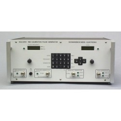
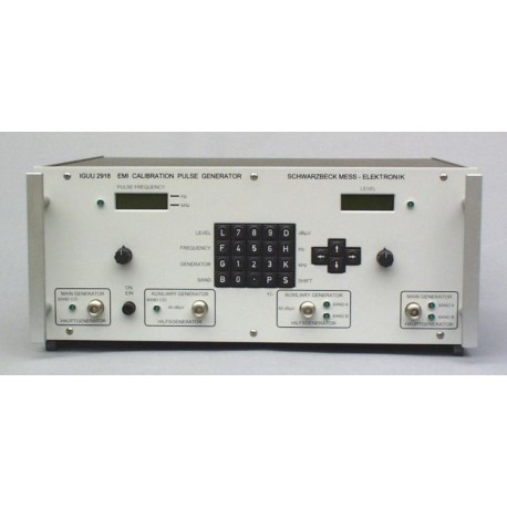
 Schwarzbeck IGUU 2918 Calibration-Pulse Generator
New
- 9 kHz-1000 MHz
- Calibration-Pulse Generator
- Acc. CISPR 16
- For Band A, B, C, D
- To calibrate the pulse response of EMI receivers.
- Pulse repetition frequency main generator 0.1 - 200 Hz (aux. generator up to 1 MHz)
- With IEEE-488 Interface.
Options
- Opt. RecTest Softw.
- Receiver Test Software
- For IGUU 2916 or 2918 signal generator and EMI-receiver
- To perform an automatic calibration of an EMI receiver acc. to CISPR 16-1-1.
PDF Downloads
Test Equipment Description

Manual operation using front panel or PC - control via GPIB - Interface
Calibration Pulse Generators are indispensable for the test of emi - receivers, especially the pulse weighting curves which are specified in the standards.
Calibration Pulse Generators up to now
For many decades the Schwarzbeck Calibration Pulse Generators IGLK 2914 (Band A, 9 kHz - 150kHz and Band B, 150kHz - 30MHz) and IGU 2912 (Band C / D, 30MHz - 1GHz) have been recognised as world wide standard. Their mechanical relay contacts generate spectrum beyond 1GHz with both high voltage and high precision. The IGUU 2916 got auxiliary generators, which opened the pulse frequency range beyond 200Hz. So finally this limit of the mechanical relay contact has been overcome. Pulse frequency in the range of 0.1Hz to 20kHz became available. This means complete testing of emi - receivers including detectors for cispr - quasi - peak, average and peak / mil.
And now the IGUU 2918
- The enhanced auxiliary generators have an extended pulse frequency range from 0.1Hz to 1MHz (Band C/D). Now it is possible to test all previous detectors and additionaly also True RMS detectors.
- Rotary encoders and matrix - displays are used for pulse frequency and amplitude (main generator only) tuning and reading. The new keypad allows a direct entry of the desired frequency and amplitude. Pulse frequency is derived from a DDS-IC.
- The optional Coaxial Switching Unit KU 9618 connects one of the four outputs of the IGUU 2918 to the e. u. t., controlled by the IGUU 2918. This is very convenient and time saving because there is no need to change coaxial connections.
- The GPIB - Interface serves for complete PC-control of all generator functions. Automatic testing is possible by using interface and coaxial switching unit KU 9618.
| Technical Data | |
| Main Generators | |
| Pulse frequency range | 0.1Hz - 200Hz in 0.1Hz steps |
| Pulse frequency accuracy | 2.3·10-3Hz |
| Pulse shape | Almost rectangular |
| Pulse duration | Band A: 270ns, |
| Band B | 6ns Band C/D: 0,3ns |
| Pulse polarity | positive/negative (switchable) |
| Pulse level | (CISPR weighting Q.P.): Band A / B 10 - 70dB, in 1dB - steps, Band C / D 0 - 60dB, in 1dB - steps |
| Max. Output Voltage acr. 50Ω | 80 V - 110 V |
| Pulse Area at 60dB attenuator setting | Corresponds to CISPR 16 Standard equivalent to 1 mVrms across 50Ω with standardized Q.P. - Detector. |
| Frequency flatness | typ. + / - 0dB to - 0.5dB at upper frequency limit for Band A / B Band C: typ. + / - 0,5dB 30 - 100MHz (100MHz is reference frequency for level calibration). Level increase Between 200MHz and 800MHz + 0,5 to + 1dB, 800 - 1000MHz decrease to + / - 0dB to - 1dB. |
| Level Accuracy | |
| Band A / B | + / - 0,5dB at 50kHz, 1MHz |
| Band C / D | + / - 0,8dB at 100MHz. |
| Auxiliary Generators | |
| Pulse frequency ranges | Band A: 0.1Hz – 2kHz Band B: 0.1Hz – 50kHz Band C/D: 0.1Hz – 1000kHz 0.1Hz – 999.9Hz, 0.1Hz steps 0.1kHz – 1000kHz, 0.1kHz steps |
| Pulse frequency accuracy | 2.3·10-3Hz |
| Pulse duration (values for orientation) | Band A: 260ns, Band B: 6.5ns, Band C / D: 500ps |
| Pulse level | ((CISPR weighting Q.P.): Band A / B 60dB fixed level Band C / D 40dB fixed level |
| Frequency flatness | Band A / B same as 1. Main Generators Band C (D): typ. + / - 0,75dB 30 – 1000MHz |
| Dimensions | W x H x D : 447mm x 180mm x 460mm |
| Weight | 12kg |
Warning
Both Main Generators of this Calibration Pulse Geerator are so powerful that they may destroy (burn out) the front end of spectrum analysers and receivers. This is also true for external preamplifiers, attenuators and any kind of auxiliary equipment. Input protection circuitry and autoranging most often do not respond fast enough and are no effective protection here. One way for safe operation is to insert a fixed attenuator between generator output and receiver input. Choose an attenuator with suitable pulse dissipation and frequency range. Increase generator output voltage slowly beginning at the lowest possible level. Increase output voltage only as high as needed for your measurement. It may sometimes occur with slow pulse frequencies (< 20Hz) that the receiver reading doesn't increase when the generator voltage increases. This is usually caused by receiver overload or saturation. In this case do not increase generator level any more. Refer to the instruction manual of the equipment under test and stay within these limits.


