
No products
Product successfully added to your shopping cart
There are 0 items in your cart. There is 1 item in your cart.
EMI Current Probes/Monitors
- EMC Test Equipment
- Transient Generators
- RF Power Amplifiers
- DC - 300 kHz RF Amplifiers
- 10 kHz - 250 MHz RF Amplifiers
- 10 kHz - 400 MHz RF Amplifiers
- 10 kHz - 1 GHz RF Amplifiers
- 80 MHz - 1 GHz RF Amplifiers
- 1 GHz - 2 GHz RF Amplifiers
- 700 MHz - 4.2 GHz RF Amplifiers
- 1 GHz - 6 GHz RF Amplifiers
- 2 GHz - 8 GHz RF Amplifiers
- 6 GHz - 18 GHz RF Amplifiers
- 18 GHz - 40 GHz RF Amplifiers
- Pulse Amplifiers
- RF Field Strength Probes & Meters
- RF Conducted Immunity
- EMC Receivers/EMI Analyzers
- EMC Antennas
- Coupling Decoupling Networks (CDN's)
- Line Impedance Stabilization Networks (LISN's)
- RF Test Equipment
- EMC Probes
- EMC Measurement & Equipment Software
- Power Supplies
- Electrical Safety Analyzers
- High Precision Laboratory Power Analyzers & Meters
- Anechoic Chambers
- Over-the-Air (OTA) Test Chambers
- EMI RF Shielded Tent Enclosures
- RF Shielded Rooms
- EMC Absorber
- Positioning Equipment
- EMC/EMI Test Setup
- GTEM Cells / TEM Cells
- Reverberation Chambers
- Used RF Anechoic Chambers
- EMC Chamber Filters
- EMC Chamber Shielding Gaskets
- RF Shielded Doors
- Anechoic Chamber Accessories
- Fully Anechoic (FAR) Test Chambers
- Manufacturers
- 3ctest
- AE Techron
- AH Systems
- Amplifier Research
- Boonton
- Com-Power
- Diamond Engineering
- EM Test (Ametek CTS)
- EMC Partner
- EMC Test Design
- Empower High Power RF Amplifiers
- ETS-lindgren
- Log Periodic Dipole Array Antenna
- Near Field Probe Sets
- Double Ridge Horn Antennas
- Biconical Antennas
- Quad Ridge Horn Antennas
- Electric Field Probes
- GTEM's
- Positioners & Tripods
- Loop Antennas
- Biconilog Antennas
- LISN's (Line Impedance Stabilization Network)
- Shielded Enclosures/Rooms
- Monopole Antennas
- Field Generating Antennas
- Fischer Custom Communications
- Haefely Hipotronics
- Haefely EFT/Burst Immunity Test Systems
- Haefely Surge Combination Wave Test Systems
- Haefely Surge Damped Oscillating Wave Test Systems
- Haefely Electrostatic Discharge Test Systems (ESD)
- Haefely Surge Ring Wave Test Systems
- Haefely Surge Telecom Wave Test Systems
- Haefely Magnetic Field Test Systems
- Haefely CDN's (Coupling/Decoupling Networks)
- IFI Amplifiers
- Keysight (Agilent)
- MVG - Microwave Vision Group
- PMM / Narda
- Rohde & Schwarz RF Test Equipment
- Rohde & Schwarz Broadband RF Amplifiers
- Rohde & Schwarz Spectrum Analyzers
- Rohde & Schwarz Compliant EMI Test Receivers
- Rohde & Schwarz Isotropic RF Probes
- Rohde & Schwarz RF Signal Generators
- Rohde & Schwarz RF Switches
- Rohde & Schwarz Oscilloscopes
- Rohde & Schwarz RF Power Meters
- Rohde & Schwarz RF Power Sensors
- Schloder
- Schwarzbeck Mess-Elektronik
- Schwarzbeck Antennas
- Schwarzbeck Automotive Antennas
- Schwarzbeck Broadband Horn Antennas
- Schwarzbeck Biconical Antennas
- Schwarzbeck Logarithmic Periodic Broadband Antennas
- Schwarzbeck Stacked Log-Periodic Broadband Antennas
- Schwarzbeck Biconic Log-Periodic Antennas
- Schwarzbeck Dipole Antennas
- Schwarzbeck Rod Antennas
- Schwarbeck Antenna Baluns / Holders
- Schwarzbeck LISN Line Impedance Stabilisation Networks
- Schwarbeck Decoupling & Absorbing Clamps
- Schwarzbeck Field Probes
- Schwarzbeck Helmholtz Coils
- Schwarzbeck Antenna Masts
- Schwarzbeck Coupling/Decoupling Networks
- Schwarzbeck Antennas
- Solar Electronics
- Teseq (Schaffner)
- Teseq Automotive Transient Generators
- Teseq RF Test Equipment
- Teseq EFT/Burst Generators
- Teseq RF Immunity Generators
- Teseq ESD Guns
- Teseq Surge Generators
- Teseq Harmonics & Flicker Solutions
- Teseq Dips, Interrupts & Variations Equipment
- Teseq Ring Wave Generators
- Teseq Oscillatory Waves Generators
- Teseq Absorbing Clamps / Ferrite Tube
- Teseq EMC Antennas
- Teseq Current Probes
- Teseq Coupling Networks
- Thermo Keytek
- Vicreate
- Compliance Standards
- International (IEC/EN)
- EN/IEC 61000-3-2
- EN/IEC 61000-3-3
- IEC 61000-3-11
- IEC / EN 610000-3-12
- EN/IEC 61000-4-2
- EN/IEC 61000-4-3
- EN/IEC 61000-4-4
- EN/IEC 61000-4-5
- EN/IEC 61000-4-6
- EN/IEC 61000-4-7
- EN/IEC 61000-4-8
- EN/IEC 61000-4-9
- EN/IEC 61000-4-10
- EN/IEC 61000-4-11
- EN/IEC 61000-4-12
- EN/IEC 61000-4-16
- EN/IEC 61000-4-18
- EN/IEC 61000-4-19
- EN/IEC 61000-4-20
- EN/IEC 61000-4-21
- EN/IEC 61000-4-29
- EN/IEC 61000-4-31
- IEC 61000-4-39
- EN/IEC 62132
- SEMI F47 Voltage Sag Immunity
- Product Standards
- Military & Aerospace Standards
- Automotive EMC Standards
- CISPR Standards
- Telecom Testing
- ANSI/IEEE Standards
- FCC Part 15
- FCC Part 30
- International (IEC/EN)
- Application/Test Type
- Radiated Immunity
- Bulk Current Injection Testing
- RF Emissions Testing
- Conducted Immunity
- Conducted Emissions
- Antenna Pattern Measurement
- CE Mark Testing
- Intentional Radiator Testing
- Pulsed HIRF Radar
- Over-the-Air (OTA) Testing
- 5G Test Solutions
- Automotive EMC
- SAR Measurement Equipment
- Radiated Emissions
- Battery Simulator Test Equipment
- Services
- Clearance
Viewed products
-

Rent Com-Power...
Frequency Range: 10 kHz to 400 MHz...
 View larger
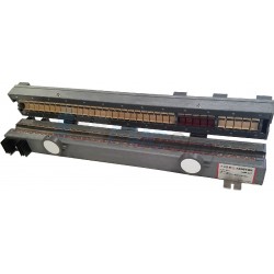
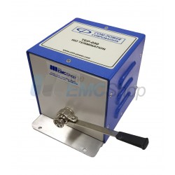
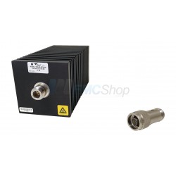
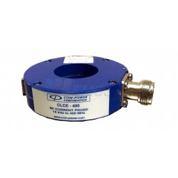
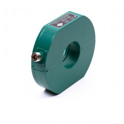
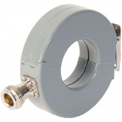
Rent Com-Power CLCE-400 Emissions Probe for CISPR, MIL-STD 461, DO-160
Refurbished
- Frequency Range: 10 kHz to 400 MHz
- Suitable for CISPR, Mil-Std 461 & DO-160
- Optional FCLCE-1000 Calibration Fixture for 50Ω transmission line
- Individual calibration
- Three-year warranty
Purchase Com-Power CLCE-400
Typically In Stock
PDF Downloads
Specifications
| Window diameter | Window (Aperture) Diameter: 1.25" (32 mm), Outside Diameter: 2.83" (72 mm) |
| Current Rating | Max Primary Current (DC-400 Hz): 100 Amps, Max Primary Current (RF): 4 Amps |
| Operating Temperature | Max. Core Temperature: 248℃F (120°C) |
| Probes Current monitoring | |
| Parameter | Value |
| Connector type | Type-N (Female) |
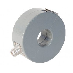
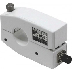
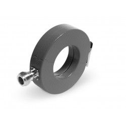
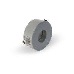
| Style | split-core ferrite in a circular hinged enclosure |
| Dimensions | Height: 0.76" (19.3 mm) |
| Weight | 0.275 lbs. (0.125 kg) |
| Frequency range | 10 kHz to 400 MHz |
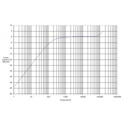
| Transfer impedance (ZT) | Transfer impedance (ZtΩ): 7Ω Transfer impedance (dBΩ): -21 to 17 dBΩ (typical) |
Test Equipment Description
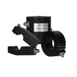
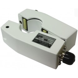
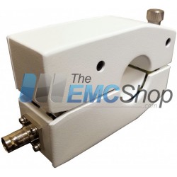
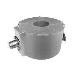
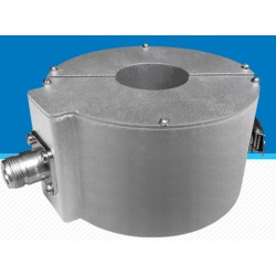
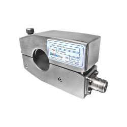
The CLCE-400 RF Current Probe is part of Com-Power's extensive line of radio frequency conducted emission/ immunity test equipment and calibration accessories. The CLCE-400 is suitable for complaince measurements required by CISPR 22, CISPR 32, DO-160, Mil Std 461 etc, as well as for applied current monitoring during conducted immunity tests.
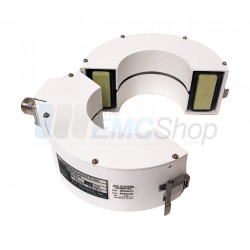
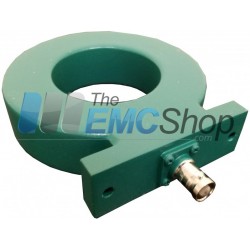
It's design incorporates a split-core ferrite in a rugged, circular hinged enclosure; thereby allowing the probe to be opened on one side in order to easily place the wire, cable(s) or cable bundle(s) to be tested into the probe window, making the CLCE-400 much more convenient to use than other non-split core probes. The CLCE-400 is designed to be used in conjunction with a spectrum analyzer or EMI receiver or any 50Ω impedance measurement equipment, which measure magnitude quantities in terms of true rms voltage.
The Transfer Impedance conversion factor, defined as the ratio of secondary voltage to the primary current, is usually expressed in terms of dB over 1Ω, It is used to convert the voltage quantity into a current quantity, expressed in terms of dB over 1 uA.
transfer impedance conversion: [dBuV] - [dBΩ] = [dBuA]
The conversion factor may also be derived from the Transfer Admittance value, expressed in terms of dB over 1 S.
transfer admittance conversion: [dBuV] + [dB(S)] = [dBuA]
Application
In general, RF current probes are employed to monitor, or measure, the asymmetrical disturbance RF currents on a wire, cable or cable bundle without making direct conductive contact with the source conductor. The current is measured inductively by clamping the probe around the conductor(s) to be tested. No actual contact is made with the conductor(s), and the insulation is left in place. Essentially, a current probe is a torroidal transformer where the conductor(s) act as a single turn primary, and the probe as a multiple turn secondary.
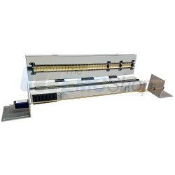
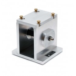
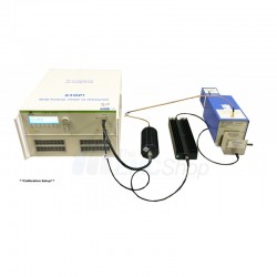
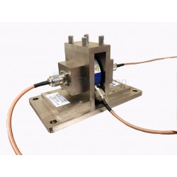
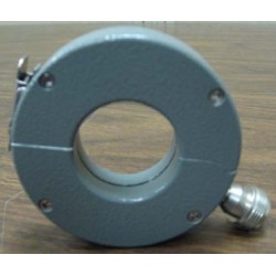
Current Probe Calibration Fixture
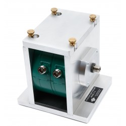
Current probes are calibrated through the use of a calibration fixture which provides a 50Ω coaxial-type transmission line arrangement. The fixture allows the probe to be clamped around the center conductor, while the outer conductor encapsulates the probe on four sides, so that the transmission line characteristics are not compromised. See calibration fixture picture on the following page.
FCLCE-1000 Calibration Fixture (optional) is specifically designed to provide a nominal 50Ω transmission line for the CLCE-400. The fixture is required for calibration of the Transfer impedance, insertion loss and VSWR parameters.
Calibration
Individual NIST traceable calibration is performed on each unit, and the data is provided along with certificate of calibration. ISO 17025 accredited calibration is available for an additional charge.
Typical Transfer Impedance Data

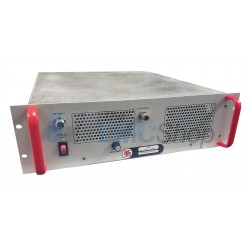
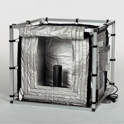
Associated EMC Test Equipment


30 other products in the same category:
-
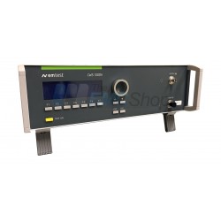
Rent 10 kHz - 400 MHz Current Monitor and Calibration Fixture
-
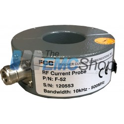
Rent Fischer F-52 Current Monitor Probe 10kHz – 500MHz
-
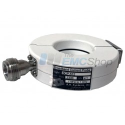
Rent AH Systems BCP-611 10 KHz – 150 MHz Broadband Current Probe
-
Fischer F-35A 100 Hz – 108 MHz Current Monitor Probe
-
AH Systems BCP-512 Probe to Measure Conducted RF Currents, 1 MHz - 1 GHz
-
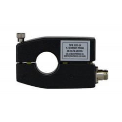
Solar Type 9123-1N RF Current Probe 10 kHz to 500 MHz
-
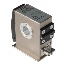
Teseq MD 4070 Monitoring Device 10 kHz to 400 (600) MHz
-
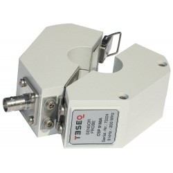
Teseq CSP 9160A EMC Emission/Immunity Sensing Probe
-
AH Systems BCP-610 High Power RF Current Probe, 20 Hz - 20 MHz
-
Fischer Custom Communications F-61 Current Monitor Probe, 1 MHz - 1 GHz
-
AH Systems BCP-614 Probe to Measure Conducted RF Currents, 10 KHz - 300 MHz
-
Narda SHC-2/1000 CISPR Passive Voltage Probes
-
Solar Type 9124-1N Clamp On Current Probe, 1 kHz - 200 MHz
-

Pearson 411 Surge Current Monitor up to 5kA Peak Current, 1Hz to 20 MHz
-

Pearson 8705C Current Probe for MIL-STD-461 CS114, CS115, CS116
-
Fischer Custom Communications F-33-1 Current Monitor Probe, 10 kHz - 250 MHz
-
Fischer Custom Communications F-51B Current Monitor Probe, 10 kHz - 500 MHz
-
Com-Power CLCE-400 Emissions Probe for CISPR, MIL-STD 461, DO-160
-
Pearson MIL-STD-461 and DO-160 Current Probe Set
-
A.H. Systems BCP-615 10 KHz – 500 MHz Broadband Current Probe
-
Pearson 101 Wide Band Current Monitor .01V/A, 0.25 Hz - 4 MHz
-
A.H. Systems BCP-611 10 KHz – 150 MHz Broadband Current Probe
-
Rent Pearson 8705C Current Probe for MIL-STD-461 CS114, CS115, CS116
-
Fischer F-33-2 Current Monitor Probe
-

Fischer F-52 Current Monitor Probe
-
AH Systems BCP-619 100 Hz - 100 MHz Broadband RF Current Probe
-
RFCP150M RF Current Montioring Probe 10k - 150M
-
RFCP300M RFI Current Sensing Probe 20 Hz to 300 MHz
-
RFCP30M Current Monitor for MIL-STD Conducted Emissions Testing
-
RFCP500M EMI Current Probe 10 kHz to 500 MHz