
No products
Product successfully added to your shopping cart
There are 0 items in your cart. There is 1 item in your cart.
Impedance Stabilization Networks (ISN's)
- EMC Test Equipment
- Transient Generators
- RF Power Amplifiers
- DC - 300 kHz RF Amplifiers
- 10 kHz - 250 MHz RF Amplifiers
- 10 kHz - 400 MHz RF Amplifiers
- 10 kHz - 1 GHz RF Amplifiers
- 80 MHz - 1 GHz RF Amplifiers
- 1 GHz - 2 GHz RF Amplifiers
- 700 MHz - 4.2 GHz RF Amplifiers
- 1 GHz - 6 GHz RF Amplifiers
- 2 GHz - 8 GHz RF Amplifiers
- 6 GHz - 18 GHz RF Amplifiers
- 18 GHz - 40 GHz RF Amplifiers
- Pulse Amplifiers
- RF Field Strength Probes & Meters
- RF Conducted Immunity
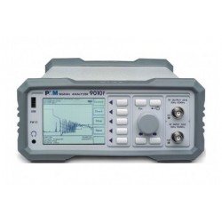
- EMC Receivers/EMI Analyzers
- EMC Antennas
- Coupling Decoupling Networks (CDN's)
- Line Impedance Stabilization Networks (LISN's)
- RF Test Equipment
- EMC Probes
- EMC Measurement & Equipment Software
- Power Supplies
- Electrical Safety Analyzers
- High Precision Laboratory Power Analyzers & Meters
- Anechoic Chambers
- Over-the-Air (OTA) Test Chambers
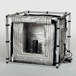
- EMI RF Shielded Tent Enclosures
- RF Shielded Rooms
- EMC Absorber
- Positioning Equipment
- EMC/EMI Test Setup
- GTEM Cells / TEM Cells
- Reverberation Chambers
- Used RF Anechoic Chambers
- EMC Chamber Filters
- EMC Chamber Shielding Gaskets
- RF Shielded Doors
- Anechoic Chamber Accessories
- Fully Anechoic (FAR) Test Chambers
- Manufacturers
- 3ctest
- AE Techron
- AH Systems
- Amplifier Research
- Boonton
- Com-Power
- Diamond Engineering
- EM Test (Ametek CTS)
- EMC Partner
- EMC Test Design
- Empower High Power RF Amplifiers
- ETS-lindgren
- Log Periodic Dipole Array Antenna
- Near Field Probe Sets
- Double Ridge Horn Antennas
- Biconical Antennas
- Quad Ridge Horn Antennas
- Electric Field Probes
- GTEM's
- Positioners & Tripods
- Loop Antennas
- Biconilog Antennas
- LISN's (Line Impedance Stabilization Network)
- Shielded Enclosures/Rooms
- Monopole Antennas
- Field Generating Antennas
- Fischer Custom Communications
- Haefely Hipotronics
- Haefely EFT/Burst Immunity Test Systems
- Haefely Surge Combination Wave Test Systems
- Haefely Surge Damped Oscillating Wave Test Systems
- Haefely Electrostatic Discharge Test Systems (ESD)
- Haefely Surge Ring Wave Test Systems
- Haefely Surge Telecom Wave Test Systems
- Haefely Magnetic Field Test Systems
- Haefely CDN's (Coupling/Decoupling Networks)
- IFI Amplifiers
- Keysight (Agilent)
- MVG - Microwave Vision Group
- PMM / Narda
- Rohde & Schwarz RF Test Equipment
- Rohde & Schwarz Broadband RF Amplifiers
- Rohde & Schwarz Spectrum Analyzers
- Rohde & Schwarz Compliant EMI Test Receivers
- Rohde & Schwarz Isotropic RF Probes
- Rohde & Schwarz RF Signal Generators
- Rohde & Schwarz RF Switches
- Rohde & Schwarz Oscilloscopes
- Rohde & Schwarz RF Power Meters
- Rohde & Schwarz RF Power Sensors
- Schloder
- Schwarzbeck Mess-Elektronik
- Schwarzbeck Antennas
- Schwarzbeck Automotive Antennas
- Schwarzbeck Broadband Horn Antennas
- Schwarzbeck Biconical Antennas
- Schwarzbeck Logarithmic Periodic Broadband Antennas
- Schwarzbeck Stacked Log-Periodic Broadband Antennas
- Schwarzbeck Biconic Log-Periodic Antennas
- Schwarzbeck Dipole Antennas
- Schwarzbeck Rod Antennas
- Schwarbeck Antenna Baluns / Holders
- Schwarzbeck LISN Line Impedance Stabilisation Networks
- Schwarbeck Decoupling & Absorbing Clamps
- Schwarzbeck Field Probes
- Schwarzbeck Helmholtz Coils
- Schwarzbeck Antenna Masts
- Schwarzbeck Coupling/Decoupling Networks
- Schwarzbeck Antennas
- Solar Electronics
- Teseq (Schaffner)
- Teseq Automotive Transient Generators
- Teseq RF Test Equipment
- Teseq EFT/Burst Generators
- Teseq RF Immunity Generators
- Teseq ESD Guns
- Teseq Surge Generators
- Teseq Harmonics & Flicker Solutions
- Teseq Dips, Interrupts & Variations Equipment
- Teseq Ring Wave Generators
- Teseq Oscillatory Waves Generators
- Teseq Absorbing Clamps / Ferrite Tube
- Teseq EMC Antennas
- Teseq Current Probes
- Teseq Coupling Networks
- Thermo Keytek
- Vicreate
- Compliance Standards
- International (IEC/EN)
- EN/IEC 61000-3-2
- EN/IEC 61000-3-3
- IEC 61000-3-11
- IEC / EN 610000-3-12
- EN/IEC 61000-4-2
- EN/IEC 61000-4-3
- EN/IEC 61000-4-4
- EN/IEC 61000-4-5
- EN/IEC 61000-4-6
- EN/IEC 61000-4-7
- EN/IEC 61000-4-8
- EN/IEC 61000-4-9
- EN/IEC 61000-4-10
- EN/IEC 61000-4-11
- EN/IEC 61000-4-12
- EN/IEC 61000-4-16
- EN/IEC 61000-4-18
- EN/IEC 61000-4-19
- EN/IEC 61000-4-20
- EN/IEC 61000-4-21
- EN/IEC 61000-4-29
- EN/IEC 61000-4-31
- IEC 61000-4-39
- EN/IEC 62132
- SEMI F47 Voltage Sag Immunity
- Product Standards
- Military & Aerospace Standards
- Automotive EMC Standards
- CISPR Standards
- Telecom Testing
- ANSI/IEEE Standards
- FCC Part 15
- FCC Part 30
- International (IEC/EN)
- Application/Test Type
- Radiated Immunity
- Bulk Current Injection Testing
- RF Emissions Testing
- Conducted Immunity
- Conducted Emissions
- Antenna Pattern Measurement
- CE Mark Testing
- Intentional Radiator Testing
- Pulsed HIRF Radar
- Over-the-Air (OTA) Testing
- 5G Test Solutions
- Automotive EMC
- SAR Measurement Equipment
- Radiated Emissions
- Battery Simulator Test Equipment
- Services
- Clearance
Viewed products
-

Teseq ISN T4A...
For use with one or two unscreened...
 for Unscreened Balanced Pairs") View larger
View larger  for Unscreened Balanced Pairs")
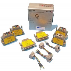
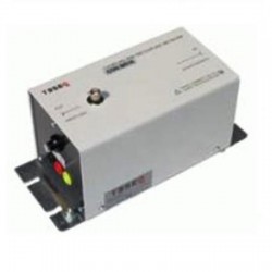
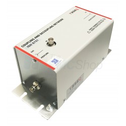
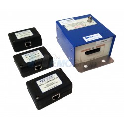
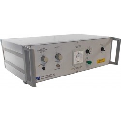
Teseq ISN T4A Impedance Stabilization Network (ISN) for Unscreened Balanced Pairs
Refurbished
- For use with one or two unscreened balanced pairs
- Refers schematic circuit example in CISPR 22/32 Figure D.2/G.2
- Intended for connection to cable category 3 and 5
- Changeable pin-arrangements with RJ11 and RJ45
- Can be used as CDN for IEC/EN 61000-4-6 immunity tests
In Stock
Specifications
| Frequency Range | 150 kHz to 80 MHz |
| RF Input Voltage | 15 V |
Test Equipment Description
Impedance stabilization networks (ISN, or with CISPR 16-1-2 called AAN: asymmetric artificial network) are defined for measuring of conducted common mode disturbances at information technology equipment (ITE) as required in CISPR 22 and CISPR 32. The ISN is placed between the equipment under test (EUT) and auxiliary equipment (AE) or load which are necessary for the operation of the EUT. The ISN establishes the common-mode termination impedance for the EUT’s telecommunications port during measurement and emulates the unsymmetrical contribution (longitudinal conversion loss, LCL) of the connected line. Different ISNs are available in relation to the line category, line numbers and pin-arrangement.
The ISN T4A is designed for measurements on one or two unscreened balanced pairs and consists of one basic network (ISN T400A) with D sub 25 connectors and special adapter sets. A set of adapters consists of LCL adapters to realize the longitudinal conversion loss (LCL)- requirements for the EUT-side in relation to the used cable category (cat. 3, cat. 5) and a connection adapter for the AE-side.
Features & Specifications of Teseq ISN T4A:
- Frequency range: 150 kHz to 80 MHz
- Line parameters: 1 or 2 pairs
Power rating (EUT and AE port)
- AC max. voltage (line to ground): 63 V
- DC max. voltage (line to ground): 100 V
- Current max.: 600 mA (line), 1200 mA (pair)
- Test voltage: 200 VDC, 2 sec
Common mode impedance (EUT port)
- 150 kHz to 30 MHz: 150 Ω ±20 Ω
- 30 MHz to 80 MHz: 150 Ω ±40 Ω
- Phase angle (EUT port) 150 kHz to 30 MHz: 0° ±20°
Coupling path (In/Out port/EUT)
- Connection: BNC 50 Ω
- RF voltage: <15 V
- Frequency range: 150 kHz to 80 MHz
Voltage division factor (RF input to EUT port)
- 150 kHz to 30 MHz: 9.5 dB ±1 dB
- 30 MHz to 80 MHz: 9.5 dB ±2 dB
- Transmission bandwidth* (wanted signal) EUT/AE B3 dB: > 100 MHz sin.
LCL (EUT) *)
- Cat. 3 150 kHz to 30 MHz (corner frequency 2 MHz): 55 dB to 39.3 dB ±3 dB
- Cat. 5 150 kHz to 2 MHz: 65 dB ±3 dB
- Cat. 5 2 MHz to 30 MHz: 65 dB to 49.3 dB +4.5/-3 dB
Decoupling of common mode disturbances (EUT/AE)
- 150 kHz to 1.5 MHz /30 MHz: ≥35 dB to ≥55 dB/≥55 dB
- Crosstalk (PSELFEXT) (EUT /AE) 1 MHz to 100 MHz: ≥61 dB to ≥21 dB
*) all balanced parameters are in relation to a symmetrical load of 100 Ω
Associated EMC Test Equipment


29 other products in the same category:
-
Teseq ISN T800S Impedance Stabilization Network per CISPR 22/32 Figure D.3/G.3
-

Rent Com-Power ISN-T8 for One, Two, Four, Unshielded Balanced Pair, CAT-3, CAT-5
-
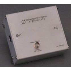
Schwarzbeck NTFM 8158 8-Wire Impedance Stabilization Network
-
Schwarzbeck CAT5 8158 8-Wire Impedance Stabilization Network
-
Teseq ISN T8 Impedance Stabilization Network (ISN) for Unscreened Balanced Pairs
-

Com-Power ISN-T8 Impedance Stabilization Network 150 kHz to 30 MHz
-
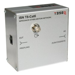
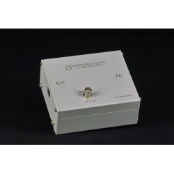
Teseq ISN T8-Cat6 Impedance Stabilization Network (ISN) for Unscreened Balanced Pairs
-
FCC CISPR 22 Impedance Stabilization Network (ISN) FCC-TLISN-T4-02
-
Com-Power ISN-T2 Impendace Stabilization Network 150 kHz to 30 MHz
-
Teseq ISN PLT Impedance Stabilization Network (ISN) for Power Line Telecommunication (PLT)
-
Teseq ISN ST08C Impedance Stabilization Network for Shielded Balanced Pairs
-

Teseq ISN S752 Impedance Stabilization Network for Coaxial Lines
-

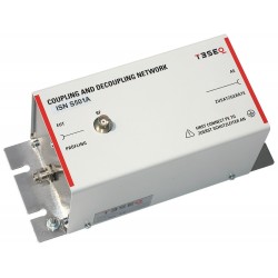
Teseq ISN S501A Impedance Stabilization Network for Coaxial Lines
-
Teseq ISN S751 Impedance Stabilization Network for Coaxial Lines
-
Teseq ISN S502A Impedance Stabilization Network for Coaxial Lines
-
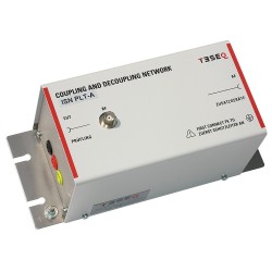
Teseq ISN PLT-A Impedance Stabilization Network (ISN) for Power Line Telecommunication (PLT)
-

Newtons4th (N4L) IMP163 Impedance Network for Harmonics & Flicker, Three Phase, 16 A
-

Newtons4th (N4L) IMP753 Impedance Network for Harmonics & Flicker, Three Phase, 75 A
-
Newtons4th (N4L) IMP323 Impedance Network for Harmonics & Flicker, Three Phase, 32 A
-

Newtons4th (N4L) IMP161 Impedance Network for Harmonics & Flicker, Single Phase, 16 A
-

Rent Teseq ISN T8 Impedance Stabilization Network (ISN) for Unscreened Balanced Pairs
-
Com-Power ISN-T8 Impendace Stabilization Network and Calibration Kit
-
Schwarzbeck NTFM 8131 2-Wire Impedance Stabilisation Network, 9 kHz - 30 MHz
-
Schwarzbeck CS-50 Unsymmetrical Splitter
-
Schwarzbeck ISN S8 Impedance Stabilisation Network
-
Chase MN2050B Line Impedance Stabilization Network (LISN)
-
Langer EMV-Technik NNB 21 Line Impedance Stabilisation Network
-
ISN30M Impedance Stabilization Network (ISN) with Coupling/Decoupling Network (CDN)
-
LISN-CISPR16-32A Line Impedance Stabilization Network