
No products
Product successfully added to your shopping cart
There are 0 items in your cart. There is 1 item in your cart.
Impedance Stabilization Networks (Power and Data Lines)
- EMC Test Equipment
- Transient Generators
- RF Power Amplifiers
- DC - 300 kHz RF Amplifiers
- 10 kHz - 250 MHz RF Amplifiers
- 10 kHz - 400 MHz RF Amplifiers
- 10 kHz - 1 GHz RF Amplifiers
- 80 MHz - 1 GHz RF Amplifiers
- 1 GHz - 2 GHz RF Amplifiers
- 700 MHz - 4.2 GHz RF Amplifiers
- 1 GHz - 6 GHz RF Amplifiers
- 2 GHz - 8 GHz RF Amplifiers
- 6 GHz - 18 GHz RF Amplifiers
- 18 GHz - 40 GHz RF Amplifiers
- Pulse Amplifiers
- RF Field Strength Probes & Meters
- RF Conducted Immunity
- EMC Receivers/EMI Analyzers
- EMC Antennas
- Coupling Decoupling Networks (CDN's)
- Line Impedance Stabilization Networks (LISN's)
- RF Test Equipment
- EMC Probes
- EMC Measurement & Equipment Software
- Power Supplies
- Electrical Safety Analyzers
- High Precision Laboratory Power Analyzers & Meters
- Anechoic Chambers
- Over-the-Air (OTA) Test Chambers
- EMI RF Shielded Tent Enclosures
- RF Shielded Rooms
- EMC Absorber
- Positioning Equipment
- EMC/EMI Test Setup
- GTEM Cells / TEM Cells
- Reverberation Chambers
- Used RF Anechoic Chambers
- EMC Chamber Filters
- EMC Chamber Shielding Gaskets
- RF Shielded Doors
- Anechoic Chamber Accessories
- Fully Anechoic (FAR) Test Chambers
- Manufacturers
- 3ctest
- AE Techron
- AH Systems
- Amplifier Research
- Boonton
- Com-Power
- Diamond Engineering
- EM Test (Ametek CTS)
- EMC Partner
- EMC Test Design
- Empower High Power RF Amplifiers
- ETS-lindgren
- Log Periodic Dipole Array Antenna
- Near Field Probe Sets
- Double Ridge Horn Antennas
- Biconical Antennas
- Quad Ridge Horn Antennas
- Electric Field Probes
- GTEM's
- Positioners & Tripods
- Loop Antennas
- Biconilog Antennas
- LISN's (Line Impedance Stabilization Network)
- Shielded Enclosures/Rooms
- Monopole Antennas
- Field Generating Antennas
- Fischer Custom Communications
- Haefely Hipotronics
- Haefely EFT/Burst Immunity Test Systems
- Haefely Surge Combination Wave Test Systems
- Haefely Surge Damped Oscillating Wave Test Systems
- Haefely Electrostatic Discharge Test Systems (ESD)
- Haefely Surge Ring Wave Test Systems
- Haefely Surge Telecom Wave Test Systems
- Haefely Magnetic Field Test Systems
- Haefely CDN's (Coupling/Decoupling Networks)
- IFI Amplifiers
- Keysight (Agilent)
- MVG - Microwave Vision Group
- PMM / Narda
- Rohde & Schwarz RF Test Equipment
- Rohde & Schwarz Broadband RF Amplifiers
- Rohde & Schwarz Spectrum Analyzers
- Rohde & Schwarz Compliant EMI Test Receivers
- Rohde & Schwarz Isotropic RF Probes
- Rohde & Schwarz RF Signal Generators
- Rohde & Schwarz RF Switches
- Rohde & Schwarz Oscilloscopes
- Rohde & Schwarz RF Power Meters
- Rohde & Schwarz RF Power Sensors
- Schloder
- Schwarzbeck Mess-Elektronik
- Schwarzbeck Antennas
- Schwarzbeck Automotive Antennas
- Schwarzbeck Broadband Horn Antennas
- Schwarzbeck Biconical Antennas
- Schwarzbeck Logarithmic Periodic Broadband Antennas
- Schwarzbeck Stacked Log-Periodic Broadband Antennas
- Schwarzbeck Biconic Log-Periodic Antennas
- Schwarzbeck Dipole Antennas
- Schwarzbeck Rod Antennas
- Schwarbeck Antenna Baluns / Holders
- Schwarzbeck LISN Line Impedance Stabilisation Networks
- Schwarbeck Decoupling & Absorbing Clamps
- Schwarzbeck Field Probes
- Schwarzbeck Helmholtz Coils
- Schwarzbeck Antenna Masts
- Schwarzbeck Coupling/Decoupling Networks
- Schwarzbeck Antennas
- Solar Electronics
- Teseq (Schaffner)
- Teseq Automotive Transient Generators
- Teseq RF Test Equipment
- Teseq EFT/Burst Generators
- Teseq RF Immunity Generators
- Teseq ESD Guns
- Teseq Surge Generators
- Teseq Harmonics & Flicker Solutions
- Teseq Dips, Interrupts & Variations Equipment
- Teseq Ring Wave Generators
- Teseq Oscillatory Waves Generators
- Teseq Absorbing Clamps / Ferrite Tube
- Teseq EMC Antennas
- Teseq Current Probes
- Teseq Coupling Networks
- Thermo Keytek
- Vicreate
- Compliance Standards
- International (IEC/EN)
- EN/IEC 61000-3-2
- EN/IEC 61000-3-3
- IEC 61000-3-11
- IEC / EN 610000-3-12
- EN/IEC 61000-4-2
- EN/IEC 61000-4-3
- EN/IEC 61000-4-4
- EN/IEC 61000-4-5
- EN/IEC 61000-4-6
- EN/IEC 61000-4-7
- EN/IEC 61000-4-8
- EN/IEC 61000-4-9
- EN/IEC 61000-4-10
- EN/IEC 61000-4-11
- EN/IEC 61000-4-12
- EN/IEC 61000-4-16
- EN/IEC 61000-4-18
- EN/IEC 61000-4-19
- EN/IEC 61000-4-20
- EN/IEC 61000-4-21
- EN/IEC 61000-4-29
- EN/IEC 61000-4-31
- IEC 61000-4-39
- EN/IEC 62132
- SEMI F47 Voltage Sag Immunity
- Product Standards
- Military & Aerospace Standards
- Automotive EMC Standards
- CISPR Standards
- Telecom Testing
- ANSI/IEEE Standards
- FCC Part 15
- FCC Part 30
- International (IEC/EN)
- Application/Test Type
- Radiated Immunity
- Bulk Current Injection Testing
- RF Emissions Testing
- Conducted Immunity
- Conducted Emissions
- Antenna Pattern Measurement
- CE Mark Testing
- Intentional Radiator Testing
- Pulsed HIRF Radar
- Over-the-Air (OTA) Testing
- 5G Test Solutions
- Automotive EMC
- SAR Measurement Equipment
- Radiated Emissions
- Battery Simulator Test Equipment
- Services
- Clearance
Viewed products
-

California Instruments...
Impedance matching network for single...
-

Rohde & Schwarz...
Frequency range: 5 kHz to 1 GHz,...
 View larger
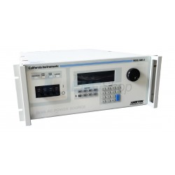
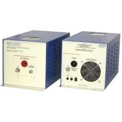
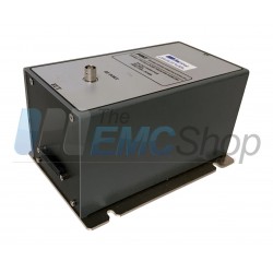
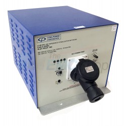
California Instruments OMNI 1-18i Impedance Matching Network
New
- Impedance matching network for single phase 5001i/iX to support IEC-1000-3-3 flicker tests
- AC Source Line Impedance Network
- Meets IEC 1000-3-3 Flicker test specification requirements
- Single and Three Phase Models
- Bypass Mode
- Remote Control Interface
In Stock
PDF Downloads
Specifications
| Application/Test Type | AC Source Line Impedance Network |
| Dimensions | 3.5” x 19” x 22” |
| Weight | 31 lbs |
Test Equipment Description
Flicker Tests; Existing IEC regulations require flicker testing for a large class of electrical and electronic equipment. Flicker occurs when the current drawn by an electrical device causes a voltage drop on the line due to the line impedance. Flicker measurements require a controlled environment. EN 61000-3-3 / IEC 1000-3-3 deals with flicker measurement requirements. This standard describes the required test setup, which includes a precision AC source having a specific impedance. By measuring the voltage drop across the standard impedance caused by the change in current drawn by the EUT (Equipment Under Test), the amount of flicker caused by the load can be determined. The characteristics of the standard impedance must be precisely controlled at the test frequency of 50 Hz.
OMNI option: The OMNI-1-18i, OMNI-3-18i and OMNI-3-37i were specifically designed to meet the IEC 1000-3-3 reference impedance requirements when used in conjunction with an i Series or iX Series AC power source. The OMNI-1-18i and OMNI3-18i are capable of handling the maximum 16 A per phase current required under the IEC standard. The OMNI-3-37i supports 32 A per phase.
Bypass Mode; Bypass mode of operation causes the reference impedance in the EUT power paths to be shunted to create virtually zero impedance. This electrically removes the reference impedance between the source and the EUT. In this mode, testing for other applications such as IEC 1000-3-2 (Harmonics) that don’t require the reference impedance is possible without physically having to disconnect it.
Engage Mode; The Engage mode activates the reference impedance path. This mode should be used for IEC 10003-3 (Flicker) test applications. The default mode of operation for the OMNI is the Bypass mode so it is important to select the correct mode of operation when performing IEC 1000-3-3 tests.
Manual Control When used with a power system that lacks direct control capability, the engage or bypass mode can be selected from the front panel. LED’s clearly indicate the status of the OMNI. At power up, the OMNI defaults to the bypass mode.
Remote Control When used with the i Series or iX Series of programmable AC power sources, the engage or bypass mode of operation are controlled from the AC Source front panel, or via the Power Source’s RS232 or IEEE 488 interface. The OMNI front panel is disabled in this case; however, the LED’s still indicate the status of the OMNI.
Functional Design; The OMNI-1-18i and OMNI-3-18i are housed in a slim line 3.5” high cabinet that matches the style of the i Series and iX Series AC power source. The OMNI-3-37i is contained in a 5.25” high cabinet. Either cabinet can be rack mounted using the included rack mount handles.
Associated EMC Test Equipment
30 other products in the same category:
-

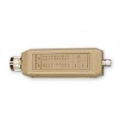
Com-Power ISN-T8 Impedance Stabilization Network 150 kHz to 30 MHz
-
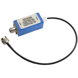
Com-Power LI-4100 10 kHz to 10 MHz Line Impedance Stabilization Network
-
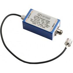
Com-Power LI-350 Line Impedance Stabilization Network
-
Com-Power LI-220A 9 kHz - 30 MHz LISN for ISPR 16-1-2/ANSI C63.4
-
Com-Power LI-3100 Line Impedance Stabilization Network
-
Intrx Three Phase Four Wire LISN for CISPR 16-1-2
-
Intrx Single Path Automotive LISN for CISPR 25, ISO 7637 and BCI Testing
-
Intrx Single Line LISN for MIL 461E/F and DO160 Requirements
-
FCC CISPR 22 Impedance Stabilization Network (ISN) FCC-TLISN-T4-02
-
Intrx LIN16-2 Single Phase Two Wire LISN for CISPR 16-1-2
-
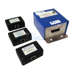
Rent Com-Power ISN-T8 for One, Two, Four, Unshielded Balanced Pair, CAT-3, CAT-5
-

Com-Power LI-3P-116 150kHz to 30MHz Three-Phase Line Impedance Stabilization Network
-

Com-Power LI-3P-132 150kHz to 30MHz Three-Phase Line Impedance Stabilization Network
-
Com-Power LI-3P-163 150kHz - 30MHz Three-Phase Line Impedance Stabilization Network
-

Com-Power LI-3P-1100 150 kHz - 30 MHz Three-Phase Line Impedance Stabilization Network
-

Com-Power LI-3P-200 Series 3-Phase LISN's with 50/250 uH Inductor, FCC/EN/CISPR, up to 100 A, 150 kHz - 30 MHz
-
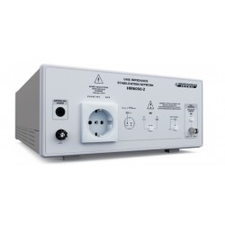
Rohde & Schwarz HM6050-2 Line Impedance Stabilization Network (LISN)
-
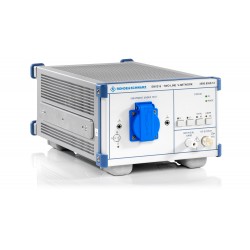
Rohde & Schwarz (R&S) ENV216 Two-Line V-Network, 9 kHz to 30 MHz, 16 Amp
-

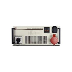
Newtons4th (N4L) IMP163 Impedance Network for Harmonics & Flicker, Three Phase, 16 A
-

Newtons4th (N4L) IMP753 Impedance Network for Harmonics & Flicker, Three Phase, 75 A
-
Newtons4th (N4L) IMP323 Impedance Network for Harmonics & Flicker, Three Phase, 32 A
-

Newtons4th (N4L) IMP161 Impedance Network for Harmonics & Flicker, Single Phase, 16 A
-
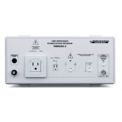
Rohde & Schwarz HM6050 Two-Line V-Network Line Impedance Stabilization Network, 9 kHz to 30 MHz, CISPR 16
-
Com-Power LI-3P-216 LISN, 9 kHz to 30 MHz, 50/250 uH, 500 VAC
-
Fischer Custom Communications FCC-LISN-5-50-1-01-MS461F, 5uH, 50 Amp, 1 Line LISN for MIL-STD-461F
-

Fischer Custom Communications FCC-LISN-50-25-1-2, 50 uH, 25 Amp, 2 Line LISN
-

Fischer Custom Communications FCC-LISN-5-50-2-01-DO-160F, 5 uH, 50 Amp, 2 Line LISN for DO-160F
-
Fischer Custom Communications FCC-LISN-50-100, 50 uH, 100 Amp, Line Impedance Stabilization Network
-
Schwarzbeck NNLK 8121 100 Amp Line Impedance Stabilization Network
-
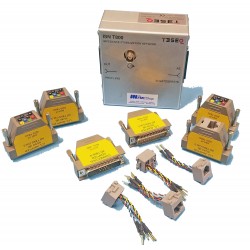
Teseq ISN T800S Impedance Stabilization Network per CISPR 22/32 Figure D.3/G.3