No products
Product successfully added to your shopping cart
There are 0 items in your cart. There is 1 item in your cart.
Surge & Burst/EFT Generators
- EMC Test Equipment
- Transient Generators
- RF Power Amplifiers
- DC - 300 kHz RF Amplifiers
- 10 kHz - 250 MHz RF Amplifiers
- 10 kHz - 400 MHz RF Amplifiers
- 10 kHz - 1 GHz RF Amplifiers
- 80 MHz - 1 GHz RF Amplifiers
- 1 GHz - 2 GHz RF Amplifiers
- 700 MHz - 4.2 GHz RF Amplifiers
- 1 GHz - 6 GHz RF Amplifiers
- 2 GHz - 8 GHz RF Amplifiers
- 6 GHz - 18 GHz RF Amplifiers
- 18 GHz - 40 GHz RF Amplifiers
- Pulse Amplifiers
- RF Field Strength Probes & Meters
- RF Conducted Immunity
- EMC Receivers/EMI Analyzers
- EMC Antennas
- Coupling Decoupling Networks (CDN's)
- Line Impedance Stabilization Networks (LISN's)
- RF Test Equipment
- EMC Probes
- EMC Measurement & Equipment Software
- Power Supplies
- Electrical Safety Analyzers
- High Precision Laboratory Power Analyzers & Meters
- Anechoic Chambers
- Over-the-Air (OTA) Test Chambers
- EMI RF Shielded Tent Enclosures
- RF Shielded Rooms
- EMC Absorber
- Positioning Equipment
- EMC/EMI Test Setup
- GTEM Cells / TEM Cells
- Reverberation Chambers
- Used RF Anechoic Chambers
- EMC Chamber Filters
- EMC Chamber Shielding Gaskets
- RF Shielded Doors
- Anechoic Chamber Accessories
- Fully Anechoic (FAR) Test Chambers
- Manufacturers
- 3ctest
- AE Techron
- AH Systems
- Amplifier Research
- Boonton
- Com-Power
- Diamond Engineering
- EM Test (Ametek CTS)
- EMC Partner
- EMC Test Design
- Empower High Power RF Amplifiers
- ETS-lindgren
- Log Periodic Dipole Array Antenna
- Near Field Probe Sets
- Double Ridge Horn Antennas
- Biconical Antennas
- Quad Ridge Horn Antennas
- Electric Field Probes
- GTEM's
- Positioners & Tripods
- Loop Antennas
- Biconilog Antennas
- LISN's (Line Impedance Stabilization Network)
- Shielded Enclosures/Rooms
- Monopole Antennas
- Field Generating Antennas
- Fischer Custom Communications
- Haefely Hipotronics
- Haefely EFT/Burst Immunity Test Systems
- Haefely Surge Combination Wave Test Systems
- Haefely Surge Damped Oscillating Wave Test Systems
- Haefely Electrostatic Discharge Test Systems (ESD)
- Haefely Surge Ring Wave Test Systems
- Haefely Surge Telecom Wave Test Systems
- Haefely Magnetic Field Test Systems
- Haefely CDN's (Coupling/Decoupling Networks)
- IFI Amplifiers
- Keysight (Agilent)
- MVG - Microwave Vision Group
- PMM / Narda
- Rohde & Schwarz RF Test Equipment
- Rohde & Schwarz Broadband RF Amplifiers
- Rohde & Schwarz Spectrum Analyzers
- Rohde & Schwarz Compliant EMI Test Receivers
- Rohde & Schwarz Isotropic RF Probes
- Rohde & Schwarz RF Signal Generators
- Rohde & Schwarz RF Switches
- Rohde & Schwarz Oscilloscopes
- Rohde & Schwarz RF Power Meters
- Rohde & Schwarz RF Power Sensors
- Schloder
- Schwarzbeck Mess-Elektronik
- Schwarzbeck Antennas
- Schwarzbeck Automotive Antennas
- Schwarzbeck Broadband Horn Antennas
- Schwarzbeck Biconical Antennas
- Schwarzbeck Logarithmic Periodic Broadband Antennas
- Schwarzbeck Stacked Log-Periodic Broadband Antennas
- Schwarzbeck Biconic Log-Periodic Antennas
- Schwarzbeck Dipole Antennas
- Schwarzbeck Rod Antennas
- Schwarbeck Antenna Baluns / Holders
- Schwarzbeck LISN Line Impedance Stabilisation Networks
- Schwarbeck Decoupling & Absorbing Clamps
- Schwarzbeck Field Probes
- Schwarzbeck Helmholtz Coils
- Schwarzbeck Antenna Masts
- Schwarzbeck Coupling/Decoupling Networks
- Schwarzbeck Antennas
- Solar Electronics
- Teseq (Schaffner)
- Teseq Automotive Transient Generators
- Teseq RF Test Equipment
- Teseq EFT/Burst Generators
- Teseq RF Immunity Generators
- Teseq ESD Guns
- Teseq Surge Generators
- Teseq Harmonics & Flicker Solutions
- Teseq Dips, Interrupts & Variations Equipment
- Teseq Ring Wave Generators
- Teseq Oscillatory Waves Generators
- Teseq Absorbing Clamps / Ferrite Tube
- Teseq EMC Antennas
- Teseq Current Probes
- Teseq Coupling Networks
- Thermo Keytek
- Vicreate
- Compliance Standards
- International (IEC/EN)
- EN/IEC 61000-3-2
- EN/IEC 61000-3-3
- IEC 61000-3-11
- IEC / EN 610000-3-12
- EN/IEC 61000-4-2
- EN/IEC 61000-4-3
- EN/IEC 61000-4-4
- EN/IEC 61000-4-5
- EN/IEC 61000-4-6
- EN/IEC 61000-4-7
- EN/IEC 61000-4-8
- EN/IEC 61000-4-9
- EN/IEC 61000-4-10
- EN/IEC 61000-4-11
- EN/IEC 61000-4-12
- EN/IEC 61000-4-16
- EN/IEC 61000-4-18
- EN/IEC 61000-4-19
- EN/IEC 61000-4-20
- EN/IEC 61000-4-21
- EN/IEC 61000-4-29
- EN/IEC 61000-4-31
- IEC 61000-4-39
- EN/IEC 62132
- SEMI F47 Voltage Sag Immunity
- Product Standards
- Military & Aerospace Standards
- Automotive EMC Standards
- CISPR Standards
- Telecom Testing
- ANSI/IEEE Standards
- FCC Part 15
- FCC Part 30
- International (IEC/EN)
- Application/Test Type
- Radiated Immunity
- Bulk Current Injection Testing
- RF Emissions Testing
- Conducted Immunity
- Conducted Emissions
- Antenna Pattern Measurement
- CE Mark Testing
- Intentional Radiator Testing
- Pulsed HIRF Radar
- Over-the-Air (OTA) Testing
- 5G Test Solutions
- Automotive EMC
- SAR Measurement Equipment
- Radiated Emissions
- Battery Simulator Test Equipment
- Services
- Clearance
Viewed products
-

Noiseken INS-4020...
0.01 ~ 2.00KV ±10% with 50 ohm load,...
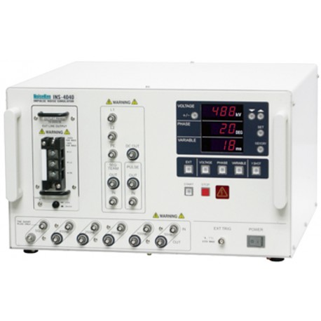 View larger
 Noiseken INS-4020 Impulse Noise Simulator
New
- 0.01 ~ 2.00KV ±10% with 50 ohm load, 10V step
- Automatic ramp operation for output voltage, phase angle and repetition period
- Floating output
- Coupling mode selection by plugging the supplied coaxial connector to the selected port
- Easily changeable mercury relay unit
- Built-in 50 ohm terminator
- Up to 5 test settings stored in the internal momory
- Easily changeable outlet panels
- CE marked
PDF Downloads
Test Equipment Description
The NoiseKen INS-4020 Noise Simulator is a further development of the INS series simulators designed for greater ease of use, durability and reliability with new technology specifically applied to this new product. The most significant addition is automatic ramp operation in output voltage, pulse repetition period and phase angle placement.
Complementary to the IEC61000-4-4, EFT/Burst test the NoiseKen INS-4020 with unique valuable features and capabilities, most of which are not met by Electrical Fast Transient/Burst generators, greatly helps to enhance your test program to ensure your products are really immune from real world phenomena.
INS SERIES ELECTRICAL SCHEMATIC

PULSE GENERATION PRINCIPLE
The main components of the pulse generator circuitry of this unit are coaxial cables, HV power supply, charging resistor, mercury relay, and terminating resistor. The coaxial cables form a distributed constant circuit consisting of the inductance of the inner conductor and capacitance between the inner and outer conductors. When this line is terminated by a 50Ω resistance, it works as a square wave pulse generator. Pulse widths vary depending on the delay time of the coaxial line (length of the cable). The proportion of pulse widths to the length is approximately 10 ns per meter. Pulse waveforms and amplitudes depend on the relation between terminator resistance and coaxial cable characteristic impedance.
The HV power supply charges up the capacitance component of the coaxial line through the charging resistor when the mercury relay is in off status. The stored energy is discharged when the mercury relay contacts turn on, generating a HV square wave pulse across the 50Ω terminating resistor. The injection unit couples this pulse through a capacitor to an EUT LINE. Also provided is a decoupling circuit consisting of an inductor and a capacitor, working as a high impedance circuit when seen from the injection point. This enables the unit to effectively couple the interference signals to the EUT and to reduce their leakage into the power supply side (LINE IN).
FOR PERFECT MATCHING
Pulse waveforms and amplitudes are dependent on the value of a termination resistor being connected to the PULSE OUT terminal. The figures and equation shown at the right show their relations. To generate square wave pulses, this unit adopts a 50Ω(strictly, 53.5Ω resistance ), an equal value to the characteristic impedance of the coaxial cables.
|
Vp=R2/(Zo+R2) x E |
| SPECIFICATIONS | |||
| INS-4020 (2kV) | INS-4040(4kV) | ||
| Output voltage | 0.01 ~ 2.00KV ±10% with 50 ohm load, 10V step | 0.01 ~ 4.00KV ±10% with 50 ohm load, 10V step | |
| Polarity | Positive or negative | ||
| Square wave | Pulse width | 50ns, 100 ns, 200ns, 250ns, 400ns, and any combination thereof, maximum width, 1µs or 10ns±3ns (the shortest connection) | |
| Pulse rise time | < 1ns | ||
| Output impedance | 50 ohm system (53.5 ohm) | ||
| Pulse repetition mode | VARIABLE | 10ms ~ 999ms±10%, 1ms step | 16ms ~ 999ms±10%, 1ms step |
| PHASE | 50 or 60Hz, Injection phase angle 0~359°, 1° step, synchronized with L1 - L2 power line frequency for EUT | ||
| EXT | <EXT mode> >10ms, Pulse width>1ms TTL/Open collector negative logic | <EXT mode> >16ms, Pulse width>1ms TTL/Open collector negative logic | |
| Also functions for timing reference signals input from an external injection unit | |||
| 1 SHOT | Single pulse injection to the angle selected by PHASE setting, or irrelevant with the EUT line frequency | ||
| Memory | Up to 5 test settings | ||
| Power capacity of equipment under test | AC 240V, DC60V, Single phase, DC60V 16A | ||
| Power supply | AC100 ~ 240V 50/60H | ||
| Power consumption | 140VA | ||
| Operating temperature and humidity | 15~35°C / 25~75% (No dewing shall occur.) | ||
| Dimensions | (W) 430 X (H) 249 X (D) 420 mm(Projections excluded) | ||
| Weight | Approx. 19kgs | ||


