
No products
Product successfully added to your shopping cart
There are 0 items in your cart. There is 1 item in your cart.
EFT Testing
- EMC Test Equipment
- Transient Generators
- RF Power Amplifiers
- DC - 300 kHz RF Amplifiers
- 10 kHz - 250 MHz RF Amplifiers
- 10 kHz - 400 MHz RF Amplifiers
- 10 kHz - 1 GHz RF Amplifiers
- 80 MHz - 1 GHz RF Amplifiers
- 1 GHz - 2 GHz RF Amplifiers
- 700 MHz - 4.2 GHz RF Amplifiers
- 1 GHz - 6 GHz RF Amplifiers
- 2 GHz - 8 GHz RF Amplifiers
- 6 GHz - 18 GHz RF Amplifiers
- 18 GHz - 40 GHz RF Amplifiers
- Pulse Amplifiers
- RF Field Strength Probes & Meters
- RF Conducted Immunity
- EMC Receivers/EMI Analyzers
- EMC Antennas
- Coupling Decoupling Networks (CDN's)
- Line Impedance Stabilization Networks (LISN's)
- RF Test Equipment
- EMC Probes
- EMC Measurement & Equipment Software
- Power Supplies
- Electrical Safety Analyzers
- High Precision Laboratory Power Analyzers & Meters
- Anechoic Chambers
- Over-the-Air (OTA) Test Chambers
- EMI RF Shielded Tent Enclosures
- RF Shielded Rooms
- EMC Absorber
- Positioning Equipment
- EMC/EMI Test Setup
- GTEM Cells / TEM Cells
- Reverberation Chambers
- Used RF Anechoic Chambers
- EMC Chamber Filters
- EMC Chamber Shielding Gaskets
- RF Shielded Doors
- Anechoic Chamber Accessories
- Fully Anechoic (FAR) Test Chambers
- Manufacturers
- 3ctest
- AE Techron
- AH Systems
- Amplifier Research
- Boonton
- Com-Power
- Diamond Engineering
- EM Test (Ametek CTS)
- EMC Partner
- EMC Test Design
- Empower High Power RF Amplifiers
- ETS-lindgren
- Log Periodic Dipole Array Antenna
- Near Field Probe Sets
- Double Ridge Horn Antennas
- Biconical Antennas
- Quad Ridge Horn Antennas
- Electric Field Probes
- GTEM's
- Positioners & Tripods
- Loop Antennas
- Biconilog Antennas
- LISN's (Line Impedance Stabilization Network)
- Shielded Enclosures/Rooms
- Monopole Antennas
- Field Generating Antennas
- Fischer Custom Communications
- Haefely Hipotronics
- Haefely EFT/Burst Immunity Test Systems
- Haefely Surge Combination Wave Test Systems
- Haefely Surge Damped Oscillating Wave Test Systems
- Haefely Electrostatic Discharge Test Systems (ESD)
- Haefely Surge Ring Wave Test Systems
- Haefely Surge Telecom Wave Test Systems
- Haefely Magnetic Field Test Systems
- Haefely CDN's (Coupling/Decoupling Networks)
- IFI Amplifiers
- Keysight (Agilent)
- MVG - Microwave Vision Group
- PMM / Narda
- Rohde & Schwarz RF Test Equipment
- Rohde & Schwarz Broadband RF Amplifiers
- Rohde & Schwarz Spectrum Analyzers
- Rohde & Schwarz Compliant EMI Test Receivers
- Rohde & Schwarz Isotropic RF Probes
- Rohde & Schwarz RF Signal Generators
- Rohde & Schwarz RF Switches
- Rohde & Schwarz Oscilloscopes
- Rohde & Schwarz RF Power Meters
- Rohde & Schwarz RF Power Sensors
- Schloder
- Schwarzbeck Mess-Elektronik
- Schwarzbeck Antennas
- Schwarzbeck Automotive Antennas
- Schwarzbeck Broadband Horn Antennas
- Schwarzbeck Biconical Antennas
- Schwarzbeck Logarithmic Periodic Broadband Antennas
- Schwarzbeck Stacked Log-Periodic Broadband Antennas
- Schwarzbeck Biconic Log-Periodic Antennas
- Schwarzbeck Dipole Antennas
- Schwarzbeck Rod Antennas
- Schwarbeck Antenna Baluns / Holders
- Schwarzbeck LISN Line Impedance Stabilisation Networks
- Schwarbeck Decoupling & Absorbing Clamps
- Schwarzbeck Field Probes
- Schwarzbeck Helmholtz Coils
- Schwarzbeck Antenna Masts
- Schwarzbeck Coupling/Decoupling Networks
- Schwarzbeck Antennas
- Solar Electronics
- Teseq (Schaffner)
- Teseq Automotive Transient Generators
- Teseq RF Test Equipment
- Teseq EFT/Burst Generators
- Teseq RF Immunity Generators
- Teseq ESD Guns
- Teseq Surge Generators
- Teseq Harmonics & Flicker Solutions
- Teseq Dips, Interrupts & Variations Equipment
- Teseq Ring Wave Generators
- Teseq Oscillatory Waves Generators
- Teseq Absorbing Clamps / Ferrite Tube
- Teseq EMC Antennas
- Teseq Current Probes
- Teseq Coupling Networks
- Thermo Keytek
- Vicreate
- Compliance Standards
- International (IEC/EN)
- EN/IEC 61000-3-2
- EN/IEC 61000-3-3
- IEC 61000-3-11
- IEC / EN 610000-3-12
- EN/IEC 61000-4-2
- EN/IEC 61000-4-3
- EN/IEC 61000-4-4
- EN/IEC 61000-4-5
- EN/IEC 61000-4-6
- EN/IEC 61000-4-7
- EN/IEC 61000-4-8
- EN/IEC 61000-4-9
- EN/IEC 61000-4-10
- EN/IEC 61000-4-11
- EN/IEC 61000-4-12
- EN/IEC 61000-4-16
- EN/IEC 61000-4-18
- EN/IEC 61000-4-19
- EN/IEC 61000-4-20
- EN/IEC 61000-4-21
- EN/IEC 61000-4-29
- EN/IEC 61000-4-31
- IEC 61000-4-39
- EN/IEC 62132
- SEMI F47 Voltage Sag Immunity
- Product Standards
- Military & Aerospace Standards
- Automotive EMC Standards
- CISPR Standards
- Telecom Testing
- ANSI/IEEE Standards
- FCC Part 15
- FCC Part 30
- International (IEC/EN)
- Application/Test Type
- Radiated Immunity
- Bulk Current Injection Testing
- RF Emissions Testing
- Conducted Immunity
- Conducted Emissions
- Antenna Pattern Measurement
- CE Mark Testing
- Intentional Radiator Testing
- Pulsed HIRF Radar
- Over-the-Air (OTA) Testing
- 5G Test Solutions
- Automotive EMC
- SAR Measurement Equipment
- Radiated Emissions
- Battery Simulator Test Equipment
- Services
- Clearance
Viewed products
-

EM Test EFT 500N5.1...
With 3-ph coupler, AC: 3x 440V/ 32A,...
-

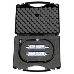
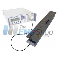
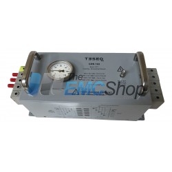
Teseq CAS ISN...
Meets CISPR 22 ed. 5.2 and CISPR...
 View larger
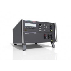
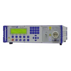
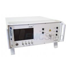
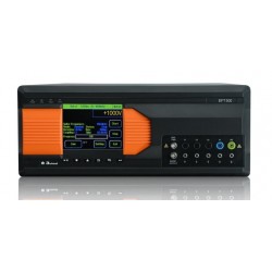
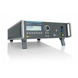
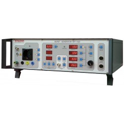
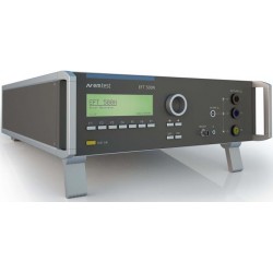
EM Test EFT 500N5.1 4.8kV Burst Generator with Built-In CDN 3x440V 32A
New
- With 3-ph coupler, AC: 3x 440V/ 32A, DC: 270V/ 32A
- 10,000 Pulses/sec.
- 4.8kV Burst Voltage
- Spike Frequency up to 1MHz
- Built-in 1ph or 3ph coupler up to 50A
- Pulse Verification acc. to Ed.3 on each coupling path
Applications:
- Industry
- Medical
- Broadcast
- Residential
PDF Downloads
Test Equipment Description
EFT/Burst Generator Pulse 5/50ns
EFT 500Nx series – an EFT/Burst generator – is an intelligent solution offering exactly what you need for full-compliance immunity tests against Electrical/Fast transients phenomena. The distinct operation features, convenient EUT connection facilities, a clearly arranged menu structure and display philosophy as well as the pre-programmed standard test routines make testing easy, reliable and safe.
Extendable by a variety of test accessories the EFT 500Nx is a universal equipment for abroad range of recommendations even for three-phase applications up to 100A.
- IEC 61000-4-4
- IEC 61000-4-4 Ed 3
- EN 61000-4-4
- EN 61000-4-4 Ed 3
Operating Functions
Front Panel | |
 | |
| 1 | Display All functions and parameters are displayed (8 lines with max. 40 characters). | 7 | ESC When pressing the ESC button the user moves back one page in the menu. |
| 2 | Function keys “F1 .. F7” Parameters and functions, displayed in the lowest line, can be selected with the related function key. | 8 | BNC CRO Trigger At the BNC output the generator trigger can be checked, e.g. the burst duration, the burst repetition rate and the spike frequency (+15 V rectangular). This output signal can also be used to trigger external measuring devices (e.g. an oscilloscope) |
| 3 | Test On By pressing the key "Test On" the test procedure is initiated with the preselected parameters. The red LED indicates the trigger of a burst event. | 9 | HV pulse output 50 ohm External coupling devices such as the capacitive coupling clamp and the coupling network CNE 503 are connected to the coaxial 50 ohm output. Also the pulse parameters, on 50Ω and 1000Ω load condition must be verified at this coaxial output. |
| 4 | Knob (Inc / Dec) The knob increments or decrements test parameters with a numeric value or selects from a list of parameters. | 10 | Ground reference During test or calibration procedure the burst generator must be grounded to the reference ground plane. |
| 5 | Cursor keys Parameters and functions can be changed on-line. The selection of these parameters is realized with the cursor moving to the left or to the right. | 11 | Coupling The LED indicates that the pulses are coupled to the L –N –PE line. |
| 6 | Exit Pressing of the Exit function will cause a reset of the firmware. This is only possible if no test routine is running. | 12 | EUT test supply The coupling / decoupling network is part of the generator. The EUT is powered via the safety laboratory plugs at the front panel of the simulator. The nominal power mains supply is 250V/16A. For higher currents, up to 100A, the external coupling network CNE 503 shall be used. |
Rear view | |
 | |
| 1 | Voltage indicator | 9 | USB interface USB interface “USB B” connector. For data transfer a USB interface is available. The internal RS 232 interface is converted to USB standard. Therefore the user must set the same Baud rate in the device and control software. Using the USB interface the user can have emc problems during burst tests Our experiences says, that usually the computer USB port is disturbed by interference’s. Therefore a high quality USB cable (USB 2.0 standard) must be used. EFT 500N8 models are equipped with an optical USB interface. |
| 2 | EUT test supply input | 10 | Remote control connector CN To remote control an external coupling matrix CNE 503. All functions are controlled by the EFT 500. It is recommended to connect and power the CNE 503 before turning the power mains ON at the EFT 500. |
| 3 | Ventilator Behind the ventilator hole a free space of at least 10cm for device cooling is necessary. | 11 | SYNC input |
| 4 | Label for serial number The serial number tag indicates additionally the operating voltage and used fuse sizes. | 12 | Reference ground connection The generator has to be connected to the reference ground plane of the test set up. Very important is the connection at the front panel of the simulator. |
| 5 | External trigger | 13 | Mains plug C14 type plug, for ac mains power 115V/240V 50/60Hz. |
| 6 | Power on switch The switch is part of the mains filter. Mains fuses are part of the filter. (230V / 1A and 115V / 2A) | 14 | Safety circuit For connect an external security circuit. |
| 7 | Mains selector Selection of 115V / 230V | 15 | Parallel interface GPIB / IEEE 488 IEEE 488 interface with IEEE connector. |
| 8 | Fuse holder Mains fuse 2-pole (phase and neutral). Fuse 5 x 20mm (230V / 1A and 115V / 2A) slow blow | 16 | Fail detection FAIL 1 (TEST STOP) The BNC input FAIL 1 can be used for DUT monitoring. In case of a low going signal (to chassis ground) the EFT 500 will stop pulse generation and the actual running test routine is paused. The test routine than can be stopped completely or can be continued from break point. A message of FAIL 1 is indicated in the LCD display as well as in the ISM ISO software. Fail detection FAIL 2 (TEST PAUSE) The BNC input FAIL 2 can be used for DUT monitoring In case of a low going signal (to chassis ground) the EFT 500 will stop pulse generation and the actual running test routine is paused as long as the low level signal is available at the FAIL 2 input. The test routine continues automatically as soon as the low level signal goes to high level. A message of FAIL 2 is indicated in the LCD display as well as in the ISM ISO software. |
 An ac voltage to which the events shall be synchronized is connected to this input. If no voltage is available the tests are started automatically in asynchronous mode with no phase angle adjust for pulse release. Normally this input shall be connected directly to L1 plug. The maximum input voltage is 300Vac.
| Technical Data | ||
| EFT Electrical Fast Transients Burst as per IEC 61000-4-4 | ||
| Test Level | N5 / N5.x | N8 / N8.x |
| Open circuit | 200V - 4800V ± 10% Step 20V | 1000V - 7000V ± 10% Step 50V |
| Wave shape into a 50Ω load | 100V - 2400V | 500V – 3500V |
| Rise time tr | 5ns ± 30% | |
| Pulse duration td | 50ns ±30% | |
| Rise time tr | 5ns ± 30% | |
| Pulse duration td | 35ns - 150ns | |
| Source impedance | Zq = 50Ω ± 20% | |
| Polarity | Positive / Negative | |
| Output | ||
| Test Level | EFT 500 N5 /N5.4 /N5.5 / N5.6 / N8 /N8.2 | EFT 500 N5.2 /N5.7 / N5.8/N8.1 |
| Direct via 50Ω coaxial connector | To connect ext. coupling devices | |
| Coupling network | To L, N, PE all combinations | |
| EUT power mains AC 50/60Hz | 250 V / 16 A N5/ N8 250 V / 32 A N5.5/ N5.6/ N8.2 690 V / 32 A N5.4 | 3 x 440V/16A EFT N5.7 3 x 440V/32A EFT N5.1/N8.1 3 x 440V/50A EFT N5.2 3 x 690V/32A EFT N5.8 |
| EUT DC power | 270V / same as AC | 270V / same as AC per line@@ |
| Max Output voltage to 3-phase coupling may be reduced | ||
| EUT power supply fuse | The EUT power supply fuse must be installed external. The fuse dimension must match the rated current of the devices EUT current | |
| Test routines | ||
| Quick Start | Immediate start, all parameters adjustable during a running test | |
| Standard test as per | IEC 61000-4-4 : N5 level 1 ... level 5 Level X - Level Y | N8: level 1 ... level 4 |
| User test routines | Customized test routines Voltage change after T by △V Frequency change after T by △f Frequency sweep in one single burst Change duration after T by △td Change polarity after T Statistical burst release Synchronized at fixed angle | |
| Safety | ||
| Safety circuit | Control input ( short circuit ) | |
| Design | as per IEC 1010, EN 61010 | |
| Interfaces | ||
| USB | USB (compatible to USB 1.1 and 2.0); optical for N8 models | |
| IEEE | Parallel, addresses 1-30 | |
| CN port | Control of CNE 503 for 3-ph testing | |
| Opto Link | Optical interface | |
| General Data | ||
| Dimensions and Weight | ||
| Device | Weight | Dimension |
| EFT 500N5 | 12.6 kg | 19" / 3 HU |
| EFT 500N5.1 | 22.4 kg | 19" / 6 HU |
| EFT 500N5.2 | ca. 40 kg | 19" / 6 HU |
| EFT 500N5.3 | 12.0 kg | 19" / 3 HU |
| EFT 500N5.4 | 20.0kg | 19" / 6 HU |
| EFT 500N5.5 | ca. 20.0kg | 19" / 6 HU |
| EFT 500N5.6 | 13.5kg | 19" / 3 HU |
| EFT 500N5.7 | 17.0kg | 19" / 6 HE |
| EFT 500N5.8 | 22.6kg | 19" / 6 HE |
| EFT 500N8 | 14.4kg | 19" / 6 HU |
| EFT 500N8.1 | ca 40 kg | 19" / 6 HU |
| EFT 500N8.2 | 20.0kg | 19" / 6 HU |
| Power supply | 115V/230V +10/-15% 50/60Hz | |
| Power supply | 115V/230V +10/-15% 50/60Hz | |
| Power | 265W max. | |
| Fuses | 230V : 2 x T 2A slow blow 115V : 2 x T 4A slow blow | |
30 other products in the same category:
-
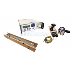
Rent Teseq CAS 3025 Burst/EFT Pulse Verification Kit
-
EM Test EFT 500N5.8 Burst Generator up to 4.8kV, w/ Built in 3-Phase Coupler, IEC 61000-4-4
-
Used Schaffner NSG 2025-4 EFT / Burst Generator Built in Three Phase Coupler
-
Used EM Test CA EFT Kit Calibration Set for EFT/Burst Generators (50 Ohm & 1 kOhm Load Resistors)
-
Haefely PEFT 8010 High Voltage EFT/Burst Generator, 7.3kV
-
Used Thermo Fisher Keytek ECAT Surge & Burst/EFT Simulator System
-
Haefely AXOS8 7kv Surge Telecom Wave Immunity Test System
-
Haefely IP4B Capacitive Coupling Clamp for EFT / Burst for Signal and Data Cables
-

Rent Schaffner CDN 8014 Burst/EFT Coupling Clamp for EN/IEC 61000-4-4
-
Rent Haefely AXOS5 Transient Immunity Test System with Surge and EFT/Burst
-
Rent Teseq (Schaffner) CDN 163 3-Phase, 100 Amp EFT/Burst Coupling Network
-
3ctest EFT 500S Burst/EFT Simulator up to 4.8 kV w/ Single Phase CDN
-

Schaffner CDN 8014 Burst/EFT Coupling Clamp for EN/IEC 61000-4-4
-
3ctest EFT 700 Burst/EFT Simulator up to 7 kV with Single or Three Phase CDN
-

EM Test CCI Capacitive EFT Coupling Clamp as per IEC 61000-4-4
-
3ctest EFT 500T Burst/EFT Simulator up to 4.8 kV w/ Three Phase CDN
-
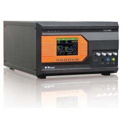
3ctest CCS 600 Conducted Immunity Test System (Surge, EFT)
-
Keytek (Thermo Fisher) CE Master for EFT, Surge, PQF
-

3ctest CCC100 EFT/Burst Coupling Clamp for IEC/EN 61000-4-4
-

Rent 3ctest CCC100 EFT/Burst Coupling Clamp for IEC/EN 61000-4-4
-
Teseq CDN 500 Capacitive Coupling Clamp for ISO 7637-3
-
EFT/Burst & ESD Rental Package for IEC 61000-4-2 and IEC 61000-4-4
-
EM Test EFT 500N5 Electrical Fast Transient/EFT/Burst Simulator
-
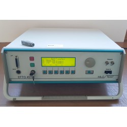
HILO TEST EFTG 4510C Burst Generator 4.4 kV 230V/50Hz Input
-
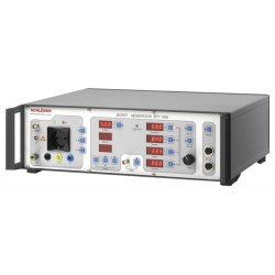
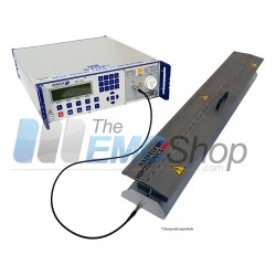
Schloder SFT 1400 E125 kHz Burst Generator
-
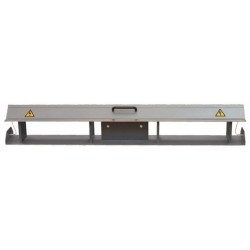
EFT-DLC EFT/Burst Capacitive Coupling Clamp for IEC/EN 61000-4-4
-
Schloder SFT 1420 2 MHz Burst Generator
-
Thermo Fisher Keytek ECAT High Voltage Burst/EFT Generator up to 8 kV
-
Used Haefely PEFT 4010 EFT/Burst Simulator for IEC/EN 61000-4-4
-
EM Test EFT 500N5.2 4.8kV Burst Generator with Built-In CDN 3x440V 50A