
No products
Product successfully added to your shopping cart
There are 0 items in your cart. There is 1 item in your cart.
EMC Test Equipment
- EMC Test Equipment
- Transient Generators
- RF Power Amplifiers
- DC - 300 kHz RF Amplifiers
- 10 kHz - 250 MHz RF Amplifiers
- 10 kHz - 400 MHz RF Amplifiers
- 10 kHz - 1 GHz RF Amplifiers
- 80 MHz - 1 GHz RF Amplifiers
- 1 GHz - 2 GHz RF Amplifiers
- 700 MHz - 4.2 GHz RF Amplifiers
- 1 GHz - 6 GHz RF Amplifiers
- 2 GHz - 8 GHz RF Amplifiers
- 6 GHz - 18 GHz RF Amplifiers
- 18 GHz - 40 GHz RF Amplifiers
- Pulse Amplifiers
- RF Field Strength Probes & Meters
- RF Conducted Immunity
- EMC Receivers/EMI Analyzers
- EMC Antennas
- Coupling Decoupling Networks (CDN's)
- Line Impedance Stabilization Networks (LISN's)
- RF Test Equipment
- EMC Probes
- EMC Measurement & Equipment Software
- Power Supplies
- Electrical Safety Analyzers
- High Precision Laboratory Power Analyzers & Meters
- Anechoic Chambers
- Over-the-Air (OTA) Test Chambers
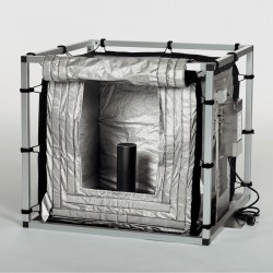
- EMI RF Shielded Tent Enclosures
- RF Shielded Rooms
- EMC Absorber
- Positioning Equipment
- EMC/EMI Test Setup
- GTEM Cells / TEM Cells
- Reverberation Chambers
- Used RF Anechoic Chambers
- EMC Chamber Filters
- EMC Chamber Shielding Gaskets
- RF Shielded Doors
- Anechoic Chamber Accessories
- Fully Anechoic (FAR) Test Chambers
- Manufacturers
- 3ctest
- AE Techron
- AH Systems
- Amplifier Research
- Boonton
- Com-Power
- Diamond Engineering
- EM Test (Ametek CTS)
- EMC Partner
- EMC Test Design
- Empower High Power RF Amplifiers
- ETS-lindgren
- Log Periodic Dipole Array Antenna
- Near Field Probe Sets
- Double Ridge Horn Antennas
- Biconical Antennas
- Quad Ridge Horn Antennas
- Electric Field Probes
- GTEM's
- Positioners & Tripods
- Loop Antennas
- Biconilog Antennas
- LISN's (Line Impedance Stabilization Network)
- Shielded Enclosures/Rooms
- Monopole Antennas
- Field Generating Antennas
- Fischer Custom Communications
- Haefely Hipotronics
- Haefely EFT/Burst Immunity Test Systems
- Haefely Surge Combination Wave Test Systems
- Haefely Surge Damped Oscillating Wave Test Systems
- Haefely Electrostatic Discharge Test Systems (ESD)
- Haefely Surge Ring Wave Test Systems
- Haefely Surge Telecom Wave Test Systems
- Haefely Magnetic Field Test Systems
- Haefely CDN's (Coupling/Decoupling Networks)
- IFI Amplifiers
- Keysight (Agilent)
- MVG - Microwave Vision Group
- PMM / Narda
- Rohde & Schwarz RF Test Equipment
- Rohde & Schwarz Broadband RF Amplifiers
- Rohde & Schwarz Spectrum Analyzers
- Rohde & Schwarz Compliant EMI Test Receivers
- Rohde & Schwarz Isotropic RF Probes
- Rohde & Schwarz RF Signal Generators
- Rohde & Schwarz RF Switches
- Rohde & Schwarz Oscilloscopes
- Rohde & Schwarz RF Power Meters
- Rohde & Schwarz RF Power Sensors
- Schloder
- Schwarzbeck Mess-Elektronik
- Schwarzbeck Antennas
- Schwarzbeck Automotive Antennas
- Schwarzbeck Broadband Horn Antennas
- Schwarzbeck Biconical Antennas
- Schwarzbeck Logarithmic Periodic Broadband Antennas
- Schwarzbeck Stacked Log-Periodic Broadband Antennas
- Schwarzbeck Biconic Log-Periodic Antennas
- Schwarzbeck Dipole Antennas
- Schwarzbeck Rod Antennas
- Schwarbeck Antenna Baluns / Holders
- Schwarzbeck LISN Line Impedance Stabilisation Networks
- Schwarbeck Decoupling & Absorbing Clamps
- Schwarzbeck Field Probes
- Schwarzbeck Helmholtz Coils
- Schwarzbeck Antenna Masts
- Schwarzbeck Coupling/Decoupling Networks
- Schwarzbeck Antennas
- Solar Electronics
- Teseq (Schaffner)
- Teseq Automotive Transient Generators
- Teseq RF Test Equipment
- Teseq EFT/Burst Generators
- Teseq RF Immunity Generators
- Teseq ESD Guns
- Teseq Surge Generators
- Teseq Harmonics & Flicker Solutions
- Teseq Dips, Interrupts & Variations Equipment
- Teseq Ring Wave Generators
- Teseq Oscillatory Waves Generators
- Teseq Absorbing Clamps / Ferrite Tube
- Teseq EMC Antennas
- Teseq Current Probes
- Teseq Coupling Networks
- Thermo Keytek
- Vicreate
- Compliance Standards
- International (IEC/EN)
- EN/IEC 61000-3-2
- EN/IEC 61000-3-3
- IEC 61000-3-11
- IEC / EN 610000-3-12
- EN/IEC 61000-4-2
- EN/IEC 61000-4-3
- EN/IEC 61000-4-4
- EN/IEC 61000-4-5
- EN/IEC 61000-4-6
- EN/IEC 61000-4-7
- EN/IEC 61000-4-8
- EN/IEC 61000-4-9
- EN/IEC 61000-4-10
- EN/IEC 61000-4-11
- EN/IEC 61000-4-12
- EN/IEC 61000-4-16
- EN/IEC 61000-4-18
- EN/IEC 61000-4-19
- EN/IEC 61000-4-20
- EN/IEC 61000-4-21
- EN/IEC 61000-4-29
- EN/IEC 61000-4-31
- IEC 61000-4-39
- EN/IEC 62132
- SEMI F47 Voltage Sag Immunity
- Product Standards
- Military & Aerospace Standards
- Automotive EMC Standards
- CISPR Standards
- Telecom Testing
- ANSI/IEEE Standards
- FCC Part 15
- FCC Part 30
- International (IEC/EN)
- Application/Test Type
- Radiated Immunity
- Bulk Current Injection Testing
- RF Emissions Testing
- Conducted Immunity
- Conducted Emissions
- Antenna Pattern Measurement
- CE Mark Testing
- Intentional Radiator Testing
- Pulsed HIRF Radar
- Over-the-Air (OTA) Testing
- 5G Test Solutions
- Automotive EMC
- SAR Measurement Equipment
- Radiated Emissions
- Battery Simulator Test Equipment
- Services
- Clearance
Viewed products
-

APELC PWTS Portable...
60 MHz, 100 MHz, 250 MHz, and 400 MHz...


APELC PWTS Portable Wideband Test Source
New
- 60 MHz, 100 MHz, 250 MHz, and 400 MHz Wideband antenna center frequencies
- Portable Wideband Test Source (PWTS)
- High-power wideband antenna system typically
- Used for MIL-STD 464 testing, IEMI susceptibility, and threat-survivability demonstrations
- For electronic equipment
Test Equipment Description
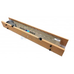
The APELC Portable Wideband Test Source (PWTS) is a high-power wideband antenna system typically used for MIL-STD 464 testing, IEMI susceptibility, and threat-survivability demonstrations for electronic equipment. Wideband antennas available with this system include center frequencies of 60 MHz, 100 MHz, 250 MHz, and 400 MHz. Each antenna can be used in vertical or horizontal polarity. The system is stored in a weather-tight insulated refrigerated trailer and deployed and erected when needed for testing.

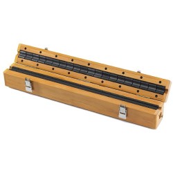
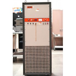
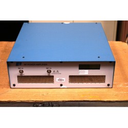
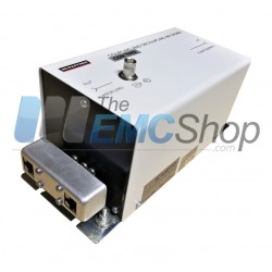
Control Rack
 |
|
Waveforms

(a) An overlay of 21 waveforms acquired during testing.
(b) The corresponding spectral density.
Control Room
 |  | ||
 |  |
MWTS
The Portable Wideband Test Source is comprised of several different subsystems:
- The PWTS radiator
- The Marx generator
- The cart and mast assembly
- The control rack
The entire system is integrated into a 48-foot refrigerated trailer comprised of a work bay and a control room. The work bay houses the PWTS radiator, the Marx generator, and the cart and mast assembly when the system is not in use. The control room houses the control rack and other ancillary systems required to safely operate the PWTS.
The PWTS radiator is comprised of a proprietary dipole antenna design that features an integrated LC resonator driving the dipole arms. The capacitance of the resonator is impulse-charged to high voltage using a Marx generator. When the resonator capacitance reaches the desired charge voltage, a spark gap (collocated with the integrated resonator) fires creating the resonance that drives the dipole arms. The dipole arm lengths are designed to be efficiently driven by the integrated resonator. The dipole antennas used in the PWTS are backed by corner reflectors to increase gain/directivity and reduce side lobes. The system is delivered with a 60-MHz dipole and collapsible corner reflector (other available antennas include the 100, 250, and 400 MHz dipoles). The Marx generator is mounted to the corner reflector frame to maintain the minimum possible Marx output cable length resulting in maximum charge delivered to the dipole resonator.
The 60-MHz dipole antenna is fastened to the corner reflector using fiberglass standoff rods. The entire dipole/reflector/Marx assembly is mounted to a cart that travels vertically along the system’s mast. The aforementioned arrangement provides the desired vertical system versatility allowing adjustment of the centerline height of up to 15-feet above the ground. The system mast facilitates not only the vertical adjustment, but also allows for minor steering of the antenna while deployed. Additionally, the mast collapses to a horizontal position resting in a cradle on a horizontal cart that enables storing the antenna inside the trailer.
| SPECIFICATION | VALUE |
| Wideband antenna center frequencies | 60 MHz 100 MHz 250 MHz 400 MHz |
| Peak electric field strength | >100 kV/m |
| Maximum system pulse repetition frequency | 100 Hz |
Associated EMC Test Equipment

30 other products in the same category:
-
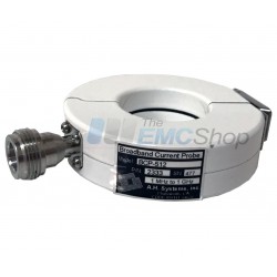
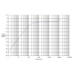
AH Systems BCP-512 Probe to Measure Conducted RF Currents, 1 MHz - 1 GHz
-
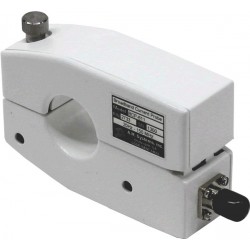
AH Systems BCP-610 High Power RF Current Probe, 20 Hz - 20 MHz
-
Rent AH Systems BCP-611 10 KHz – 150 MHz Broadband Current Probe
-
Haefely IP4A Capacitive Coupling Clamp for IEC 61000-4-4
-
Com-Power CLA-050 10mm Absorbing Clamp
-
Rent Amplifier Research 2000LM20, 1 - 200 MHz, 2 kW RF Power Amp
-
Monthly Rental: E&I / ENI 2200L 200W RF Power Amplifier 10 kHz - 12 MHz
-
EMCO (ETS-Lindgren) 3810-2 LISN, NEMA, 9 kHz - 30 MHz, 10 Amps
-
Rent Haefely PSURGE 4010 Surge Generator for IEC 61000-4-5 Testing
-
Rent Haefely PIM 100 Combination Wave Impulse Module for IEC 61000-4-5 and ANSI C62.41
-
Rent Haefely PSURGE 8000/PIM 150 Ring Wave & Damp Oscillating Wave Impulse System
-
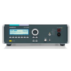
Rent EM Test UCS 200N50 ISO 7637 EMC Generator for Automotive Waveforms 1,2a, 3a, 3b
-
Haefely PEFT 8010 High Voltage EFT/Burst Generator, 7.3kV
-
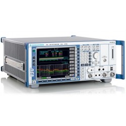
Rent Rohde & Schwarz ESU40 EMI Test Receiver for CISPR and MIL-STD Testing
-
Rent Haefely ONYX 30 ESD Simulator Gun
-
Monthly Rental Teseq (Schaffner) CDN T002 Coupling Network for Unshielded Balanced Pairs
-
Rent Haefely ECOMPACT4 Surge & EFT/Burst Simulator for IEC 61000-4-4 and 4-5
-
Rent Keytek ECAT Ring Wave Simulator for ANSI/IEEE C62.4 and UL 864
-
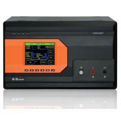
3ctest SG 5010H 10kV Surge Simulator for IEC 61000-4-5, GB/T, ITU-T K21/K44
-
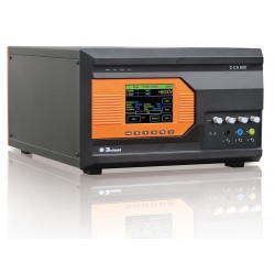
3ctest CCS 600 Conducted Immunity Test System (Surge, EFT)
-
3ctest LSS 160SS Single Stroke Test System for DO-160 Section 22 Pulses 1, 4, 5A, 5B
-
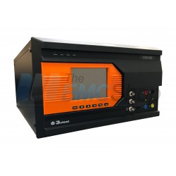
3ctest CWS 600T 10/700us Telecom Wave Surge Simulator for IEC 61000-4-5
-
Rent 3ctest CWS 600 6kV Surge Simulator for IEC 61000-4-5
-
3ctest CWS 600CT Combination Wave & Telecom Surge Simulator, 1.2/50us 8/20us 10/700us 5/320us
-
AH Systems CPF-631 Current Probe Calibration Fixture
-
Rent EM Test ESD NX30 Electrostatic Discharge Simulator Gun System for up to 30kV Testing
-
AH Systems BCP-614 Probe to Measure Conducted RF Currents, 10 KHz - 300 MHz
-
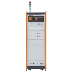
Com-Power Turn Key Conducted Immunity Test System up to 250 MHz
-
Com-Power ISN-T8 Impedance Stabilization Network 150 kHz to 30 MHz
-
Rent 3ctest TIS 700 Automotive Transient Simulator ISO 7637 Pulse 1,2a,3a/b