
No products
Product successfully added to your shopping cart
There are 0 items in your cart. There is 1 item in your cart.
EMC Test Equipment
- EMC Test Equipment
- Transient Generators
- RF Power Amplifiers
- DC - 300 kHz RF Amplifiers
- 10 kHz - 250 MHz RF Amplifiers
- 10 kHz - 400 MHz RF Amplifiers
- 10 kHz - 1 GHz RF Amplifiers
- 80 MHz - 1 GHz RF Amplifiers
- 1 GHz - 2 GHz RF Amplifiers
- 700 MHz - 4.2 GHz RF Amplifiers
- 1 GHz - 6 GHz RF Amplifiers
- 2 GHz - 8 GHz RF Amplifiers
- 6 GHz - 18 GHz RF Amplifiers
- 18 GHz - 40 GHz RF Amplifiers
- Pulse Amplifiers
- RF Field Strength Probes & Meters
- RF Conducted Immunity
- EMC Receivers/EMI Analyzers
- EMC Antennas
- Coupling Decoupling Networks (CDN's)
- Line Impedance Stabilization Networks (LISN's)
- RF Test Equipment
- EMC Probes
- EMC Measurement & Equipment Software
- Power Supplies
- Electrical Safety Analyzers
- High Precision Laboratory Power Analyzers & Meters
- Anechoic Chambers
- Over-the-Air (OTA) Test Chambers
- EMI RF Shielded Tent Enclosures
- RF Shielded Rooms
- EMC Absorber
- Positioning Equipment
- EMC/EMI Test Setup
- GTEM Cells / TEM Cells
- Reverberation Chambers
- Used RF Anechoic Chambers
- EMC Chamber Filters
- EMC Chamber Shielding Gaskets
- RF Shielded Doors
- Anechoic Chamber Accessories
- Fully Anechoic (FAR) Test Chambers
- Manufacturers
- 3ctest
- AE Techron
- AH Systems
- Amplifier Research
- Boonton
- Com-Power
- Diamond Engineering
- EM Test (Ametek CTS)
- EMC Partner
- EMC Test Design
- Empower High Power RF Amplifiers
- ETS-lindgren
- Log Periodic Dipole Array Antenna
- Near Field Probe Sets
- Double Ridge Horn Antennas
- Biconical Antennas
- Quad Ridge Horn Antennas
- Electric Field Probes
- GTEM's
- Positioners & Tripods
- Loop Antennas
- Biconilog Antennas
- LISN's (Line Impedance Stabilization Network)
- Shielded Enclosures/Rooms
- Monopole Antennas
- Field Generating Antennas
- Fischer Custom Communications
- Haefely Hipotronics
- Haefely EFT/Burst Immunity Test Systems
- Haefely Surge Combination Wave Test Systems
- Haefely Surge Damped Oscillating Wave Test Systems
- Haefely Electrostatic Discharge Test Systems (ESD)
- Haefely Surge Ring Wave Test Systems
- Haefely Surge Telecom Wave Test Systems
- Haefely Magnetic Field Test Systems
- Haefely CDN's (Coupling/Decoupling Networks)
- IFI Amplifiers
- Keysight (Agilent)
- MVG - Microwave Vision Group
- PMM / Narda
- Rohde & Schwarz RF Test Equipment
- Rohde & Schwarz Broadband RF Amplifiers
- Rohde & Schwarz Spectrum Analyzers
- Rohde & Schwarz Compliant EMI Test Receivers
- Rohde & Schwarz Isotropic RF Probes
- Rohde & Schwarz RF Signal Generators
- Rohde & Schwarz RF Switches
- Rohde & Schwarz Oscilloscopes
- Rohde & Schwarz RF Power Meters
- Rohde & Schwarz RF Power Sensors
- Schloder
- Schwarzbeck Mess-Elektronik
- Schwarzbeck Antennas
- Schwarzbeck Automotive Antennas
- Schwarzbeck Broadband Horn Antennas
- Schwarzbeck Biconical Antennas
- Schwarzbeck Logarithmic Periodic Broadband Antennas
- Schwarzbeck Stacked Log-Periodic Broadband Antennas
- Schwarzbeck Biconic Log-Periodic Antennas
- Schwarzbeck Dipole Antennas
- Schwarzbeck Rod Antennas
- Schwarbeck Antenna Baluns / Holders
- Schwarzbeck LISN Line Impedance Stabilisation Networks
- Schwarbeck Decoupling & Absorbing Clamps
- Schwarzbeck Field Probes
- Schwarzbeck Helmholtz Coils
- Schwarzbeck Antenna Masts
- Schwarzbeck Coupling/Decoupling Networks
- Schwarzbeck Antennas
- Solar Electronics
- Teseq (Schaffner)
- Teseq Automotive Transient Generators
- Teseq RF Test Equipment
- Teseq EFT/Burst Generators
- Teseq RF Immunity Generators
- Teseq ESD Guns
- Teseq Surge Generators
- Teseq Harmonics & Flicker Solutions
- Teseq Dips, Interrupts & Variations Equipment
- Teseq Ring Wave Generators
- Teseq Oscillatory Waves Generators
- Teseq Absorbing Clamps / Ferrite Tube
- Teseq EMC Antennas
- Teseq Current Probes
- Teseq Coupling Networks
- Thermo Keytek
- Vicreate
- Compliance Standards
- International (IEC/EN)
- EN/IEC 61000-3-2
- EN/IEC 61000-3-3
- IEC 61000-3-11
- IEC / EN 610000-3-12
- EN/IEC 61000-4-2
- EN/IEC 61000-4-3
- EN/IEC 61000-4-4
- EN/IEC 61000-4-5
- EN/IEC 61000-4-6
- EN/IEC 61000-4-7
- EN/IEC 61000-4-8
- EN/IEC 61000-4-9
- EN/IEC 61000-4-10
- EN/IEC 61000-4-11
- EN/IEC 61000-4-12
- EN/IEC 61000-4-16
- EN/IEC 61000-4-18
- EN/IEC 61000-4-19
- EN/IEC 61000-4-20
- EN/IEC 61000-4-21
- EN/IEC 61000-4-29
- EN/IEC 61000-4-31
- IEC 61000-4-39
- EN/IEC 62132
- SEMI F47 Voltage Sag Immunity
- Product Standards
- Military & Aerospace Standards
- Automotive EMC Standards
- CISPR Standards
- Telecom Testing
- ANSI/IEEE Standards
- FCC Part 15
- FCC Part 30
- International (IEC/EN)
- Application/Test Type
- Radiated Immunity
- Bulk Current Injection Testing
- RF Emissions Testing
- Conducted Immunity
- Conducted Emissions
- Antenna Pattern Measurement
- CE Mark Testing
- Intentional Radiator Testing
- Pulsed HIRF Radar
- Over-the-Air (OTA) Testing
- 5G Test Solutions
- Automotive EMC
- SAR Measurement Equipment
- Radiated Emissions
- Battery Simulator Test Equipment
- Services
- Clearance
Viewed products
-

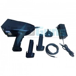
Langer EMV-Technik S2...
Contains active and passive magnetic...


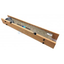
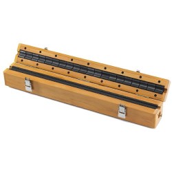
Langer EMV-Technik S2 Set Magnetic Field Probes For E1
New
- Contains active and passive magnetic field probes
- They measure the nonreactive fast transient pulse magnetic fields in electonic devices
- Assemblies under interference
- Transmit the measured signals via the LWL connection to the optical receiver of the SGZ 21
- Used with the SGZ 21 burst generator
PDF Downloads
Test Equipment Description
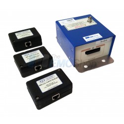
The S2 set contains active and passive magnetic field probes. They measure the nonreactive fast transient pulse magnetic fields in electonic devices and assemblies under interference. Burst and ESD processes, which cause problems in the device under test, can be analyzed. The magnetic field probes transmit the measured signals via the LWL connection to the optical receiver of the SGZ 21. The S2 set can only be used with the SGZ 21 burst generator.
Scope of delivery
1x MSA 02, Magnetic Field Probe (active)
1x 05K black, Probe Head for MSA 02
1x 05R white, Probe Head for MSA 02
1x 05U orange, Probe Head for MSA 02
1x MS 101, Magnetic Field Probe
1x MS 102U, Magnetic Field Probe
1x S2 case, System Case
1x S2 m, S2 Set User Manual
Usage
For disturbance immunity problems (Burst/ESD), it was previously not possible to measure pulse current and magnetic pulse fields to assist fault identification. This was due to the extreme measuring conditions. During Burst or ESD events, measurement must be made with field strengths of 100 kV/m and pulse rise times of a few nanoseconds. Normal measuring technology, like oscilloscopes with 50 Ohm measuring leads, is not suitable for this. Extremely small and disturbance-immune probes without any electrical leads are necessary. HF and potential isolation via optical fibre is a prerequisite. With the magnetic field probes in the S2 probe set, fast transient magnetic pulse fields and pulse currents are measurable in electronic equipment and on electronic modules under extreme disturbance influence. The aim of the usage is the clarification of disturbance immunity phenomena resulting from Burst or ESD events. Targeted corrective measures can be identified from the distribution of the pulse current and magnetic pulse field measured on the module or in the equipment. The probes can only be used in conjunction with an optical fibre and optical evaluation.
Disturbance source burst generator
To make the measuring of magnetic field and current disturbance possible, these must be simulated in the unit under test.
Pulse rate procedure
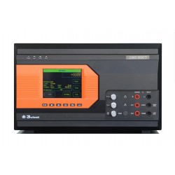
The SGZ 21 burst generator contained in the E1 disturbance immunity development system makes this procedure possible. The unit under test is injected with pulses from the SGZ 21 burst generator so as to generate disturbance currents and magnetic field disturbance. The intensity of current and magnetic field can only be measured with the pulse rate procedure.

Figure 1 Pulse rate procedure with SGZ 21 burst generator and MSA 02
Threshold procedure
By using a burst generator according to EN 61000-4-4, a magnetic pulse field can be identified with a threshold value. Either the pulse rate counter of the SGZ 21 generator or the optical receiver OE 150 of the OSE optical signal acquisition, is to be used as indicating equipment.

Figure 2 Threshold procedure with MSA 02, SGZ 21 and
EFT burst generator according to EN 61000-4-4
Disturbance mechanisms
- Electronic modules have, depending on layout and IC-sensitivity, different levels of disturbance immunity.
- Precisely definable weak spots are the cause of Burst and ESD sensitivity. The formation of such weak spots depends mainly on the GND/Vcc/signal track geometry and the type/manufacturer of the IC utilized.
- Disturbance pulse current (I) infiltrates electronic modules via conductors or capacitance. Electric disturbance fields (electric field strength E) or magnetic disturbance fields (magnetic flux density B) caused by the disturbance current radiating the surface of the modules.
- Magnetic pulse fields (B) or electric pulse fields (E) are the major physical quantities which cause flat modules to be influenced.
- A weak spot is normally only magnetic sensitive or only electric-sensitive.
- In practice, both weak spot types are relevant. For example, in disturbance events, electric fields which influence electric-sensitive weak spots can occur. The currents driven by the electric field can themselves produce magnetic fields which influence magnetic sensitive weak spots (Figure 3).
- The disturbance effects of the two mechanisms overlap and are difficult to separate.
- Due to the different physical mechanisms each of the two weak-spot types requires different EMC measures.
- Usually, only a few disturbance immunity weak spots exist on one module and these are often confined to small surface areas.
- The module is immune to disturbance when these weak spots are located and corrected.
- The burst magnetic fields radiating on the module surface or within equipment spaces can be measured with special magnetic field probes without reverse reaction (S2 set).
- With the EMC sensors, reference disturbance thresholds can be modeled and influenced logical signals captured (E1, OSE 150).

Figure 3 Field Distributions
Disturbance current (i) infiltrates the unit via the input cable. The internal disturbance current (iI) is reduced by the bypass current part (iA) leaving the unit via the bypass capacitor (C) current paths. The magnetic fields B shown in the illustration Fehler! Verweisquelle konnte nicht gefunden werden. can influence electronic modules located within some decimetres. Not all B fields infiltrating the module surface have an influencing effect. Usually, only small areas are B-field sensitive. To be observed is that magnetic fields are not only produced by disturbance current (i) in the area of feed cables and PE connections. Participating to a large extent are also bypass capacitor (C) current paths and internal GND and Vcc connections.
Electric pulse fields (E) are radiated from the leads carrying the disturbance current and these mainly influence signal connections which have a high-impedance signal source.
Functioning
Disturbance current is injected into the unit under test over the generator leads from the SGZ 21 burst generator. The resulting magnetic pulse field induces a voltage pulse in the probe’s induction coil. This is amplified and converted into an optical signal. The optical signal is fed to the optical receiver of the pulse rate counter via the optical fibre. The indicated value is proportional to the magnetic flux density and the disturbance current. The counter indicates a higher pulse rate when the magnetic field probe is placed into an area with greater field strength. The count value provides a comparison measurement for development-accompanying measurements.

Figure 4 Pulse Rate Procedure
Disturbance current is injected into the unit under test over the generator leads from the SGZ 21 burst generator. The resulting magnetic pulse field induces a voltage pulse in the probe’s induction coil. This is amplified and converted into an optical signal. The optical signal is fed
Associated EMC Test Equipment

30 other products in the same category:
-
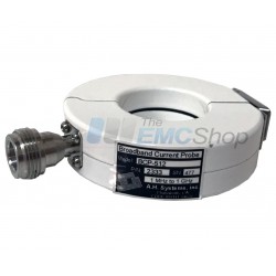
AH Systems BCP-512 Probe to Measure Conducted RF Currents, 1 MHz - 1 GHz
-
AH Systems BCP-610 High Power RF Current Probe, 20 Hz - 20 MHz
-
Rent AH Systems BCP-611 10 KHz – 150 MHz Broadband Current Probe
-
Haefely IP4A Capacitive Coupling Clamp for IEC 61000-4-4
-
Com-Power CLA-050 10mm Absorbing Clamp
-
Rent Amplifier Research 2000LM20, 1 - 200 MHz, 2 kW RF Power Amp
-
Monthly Rental: E&I / ENI 2200L 200W RF Power Amplifier 10 kHz - 12 MHz
-
EMCO (ETS-Lindgren) 3810-2 LISN, NEMA, 9 kHz - 30 MHz, 10 Amps
-
Rent Haefely PSURGE 4010 Surge Generator for IEC 61000-4-5 Testing
-
Rent Haefely PIM 100 Combination Wave Impulse Module for IEC 61000-4-5 and ANSI C62.41
-
Rent Haefely PSURGE 8000/PIM 150 Ring Wave & Damp Oscillating Wave Impulse System
-
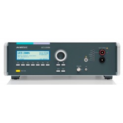
Rent EM Test UCS 200N50 ISO 7637 EMC Generator for Automotive Waveforms 1,2a, 3a, 3b
-
Haefely PEFT 8010 High Voltage EFT/Burst Generator, 7.3kV
-
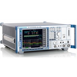
Rent Rohde & Schwarz ESU40 EMI Test Receiver for CISPR and MIL-STD Testing
-
Rent Haefely ONYX 30 ESD Simulator Gun
-
Monthly Rental Teseq (Schaffner) CDN T002 Coupling Network for Unshielded Balanced Pairs
-
Rent Haefely ECOMPACT4 Surge & EFT/Burst Simulator for IEC 61000-4-4 and 4-5
-
Rent Keytek ECAT Ring Wave Simulator for ANSI/IEEE C62.4 and UL 864
-
3ctest SG 5010H 10kV Surge Simulator for IEC 61000-4-5, GB/T, ITU-T K21/K44
-
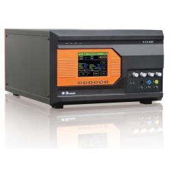
3ctest CCS 600 Conducted Immunity Test System (Surge, EFT)
-
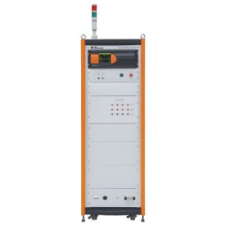
3ctest LSS 160SS Single Stroke Test System for DO-160 Section 22 Pulses 1, 4, 5A, 5B
-
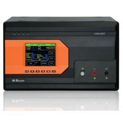
3ctest CWS 600T 10/700us Telecom Wave Surge Simulator for IEC 61000-4-5
-
Rent 3ctest CWS 600 6kV Surge Simulator for IEC 61000-4-5
-
3ctest CWS 600CT Combination Wave & Telecom Surge Simulator, 1.2/50us 8/20us 10/700us 5/320us
-
AH Systems CPF-631 Current Probe Calibration Fixture
-
Rent EM Test ESD NX30 Electrostatic Discharge Simulator Gun System for up to 30kV Testing
-
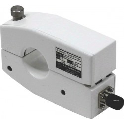
AH Systems BCP-614 Probe to Measure Conducted RF Currents, 10 KHz - 300 MHz
-
Com-Power Turn Key Conducted Immunity Test System up to 250 MHz
-
Com-Power ISN-T8 Impedance Stabilization Network 150 kHz to 30 MHz
-
Rent 3ctest TIS 700 Automotive Transient Simulator ISO 7637 Pulse 1,2a,3a/b